2.5 Network Communication Interfaces |
|
|
| |
2.5.1 |
| Pin | Name | Description |
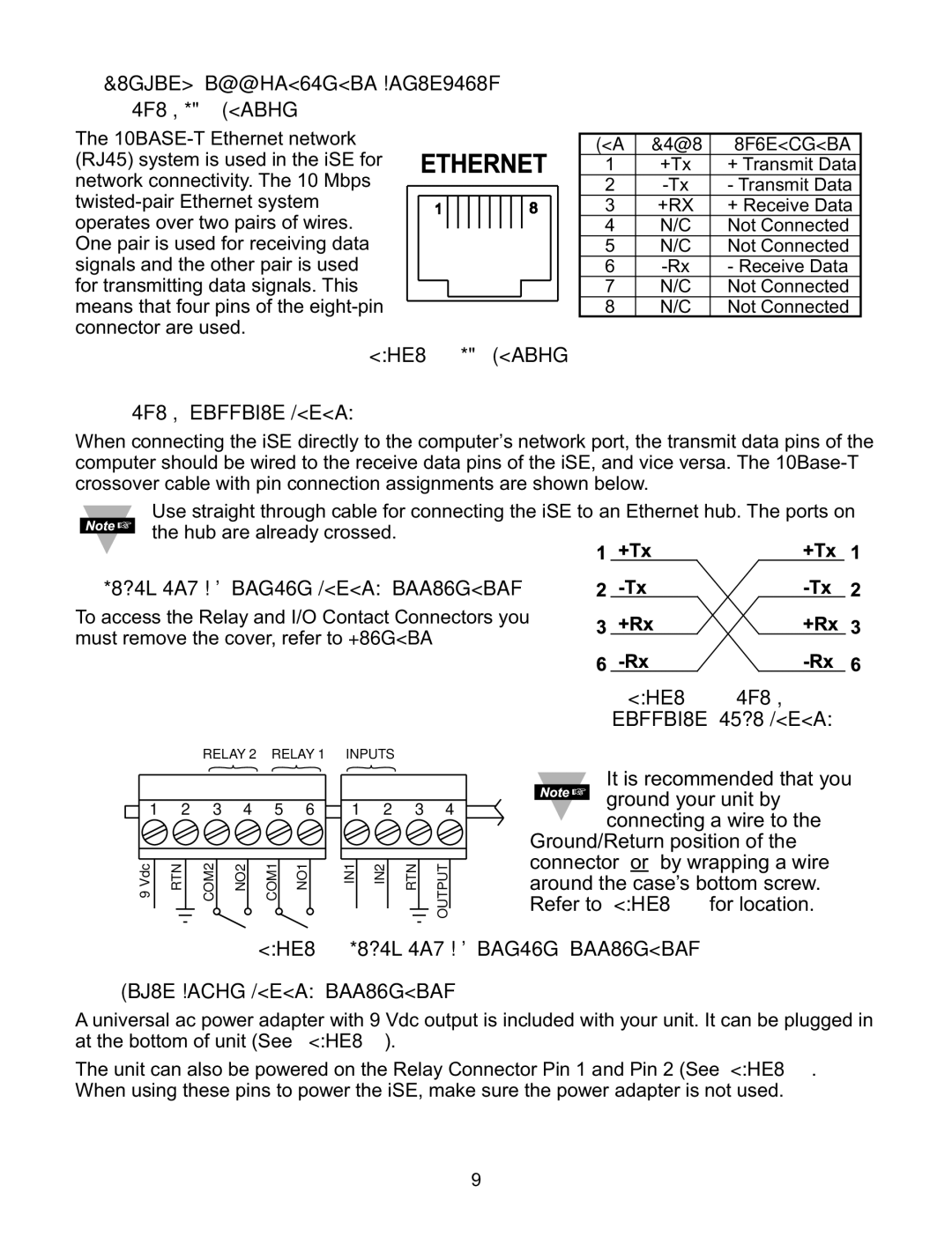
The |
| |||
(RJ45) system is used in the iSE for | 1 | +Tx | + Transmit Data | |
network connectivity. The 10 Mbps | 2 | - Transmit Data | ||
| 3 | +RX | + Receive Data | |
operates over two pairs of wires. |
| 4 | N/C | Not Connected |
One pair is used for receiving data | 5 | N/C | Not Connected | |
signals and the other pair is used |
| 6 | - Receive Data | |
for transmitting data signals. This |
| 7 | N/C | Not Connected |
means that four pins of the | 8 | N/C | Not Connected | |
connector are used. | Figure 2.6 RJ45 Pinout |
|
|
|
|
|
|
| |
2.5.2 |
|
|
|
|
|
|
| ||||||||||||||||||||||||||||||
When connecting the iSE directly to the computer’s network port, the transmit data pins of the | |||||||||||||||||||||||||||||||||||||
computer should be wired to the receive data pins of the iSE, and vice versa. The | |||||||||||||||||||||||||||||||||||||
crossover cable with pin connection assignments are shown below. | |||||||||||||||||||||||||||||||||||||
|
|
|
|
| Use straight through cable for connecting the iSE to an Ethernet hub. The ports on | ||||||||||||||||||||||||||||||||
|
|
|
|
| the hub are already crossed. |
|
|
|
|
|
|
| |||||||||||||||||||||||||
|
|
|
|
|
|
|
|
|
|
|
| ||||||||||||||||||||||||||
|
|
|
|
|
|
|
|
|
|
|
| ||||||||||||||||||||||||||
2.6 Relay and I/O Contact Wiring Connections |
|
|
|
|
|
|
| ||||||||||||||||||||||||||||||
|
|
|
|
|
|
| |||||||||||||||||||||||||||||||
To access the Relay and I/O Contact Connectors you |
|
|
|
|
|
|
| ||||||||||||||||||||||||||||||
must remove the cover, refer to Section 2.4. |
|
|
|
|
|
|
| ||||||||||||||||||||||||||||||
|
|
|
|
|
|
| |||||||||||||||||||||||||||||||
|
|
|
|
|
|
|
|
|
|
|
|
|
|
|
|
|
|
|
|
|
|
|
|
|
|
|
|
|
|
|
|
|
| Figure 2.7 | |||
|
|
|
|
|
|
|
|
|
|
| RELAY 2 | RELAY 1 |
| INPUTS |
|
| Crossover Cable Wiring | ||||||||||||||||||||
|
|
|
|
|
|
|
|
|
|
|
|
|
| It is recommended that you | |||||||||||||||||||||||
|
|
|
|
|
|
|
|
|
|
|
|
|
|
|
|
|
|
|
|
|
|
|
|
|
|
|
|
|
|
|
|
| |||||
|
|
|
|
|
|
|
|
|
|
|
|
|
|
|
|
|
|
|
|
|
|
|
|
|
|
|
|
|
|
| |||||||
|
|
|
|
|
|
|
|
|
|
|
|
|
|
|
|
|
|
|
|
|
|
|
|
|
|
|
|
|
|
|
|
| ground your unit by | ||||
|
|
| 1 2 3 4 | 5 6 | 1 2 3 4 |
|
|
| |||||||||||||||||||||||||||||
|
|
|
|
|
| connecting a wire to the | |||||||||||||||||||||||||||||||
|
| ||||||||||||||||||||||||||||||||||||
|
|
|
|
|
|
|
|
|
|
|
|
|
|
|
|
|
|
|
|
|
|
|
|
|
|
|
|
|
|
| Ground/Return position of the | ||||||
|
|
|
|
|
|
|
|
|
|
|
|
|
|
|
|
|
|
|
|
|
|
|
|
|
|
|
|
|
|
| connector or by wrapping a wire | ||||||
|
|
|
|
|
|
|
|
|
|
|
|
|
|
|
|
|
|
|
|
|
|
|
|
|
|
|
|
|
|
| |||||||
| 9Vdc | RTN | COM2 | NO2 | COM1 | NO1 |
| IN1 |
| IN2 |
| RTN |
|
| OUTPUT |
|
|
| around the case’s bottom screw. | ||||||||||||||||||
|
|
|
|
|
|
|
| Refer to Figure 3.1 for location. | |||||||||||||||||||||||||||||
|
|
|
|
|
|
|
|
|
|
|
|
|
|
|
|
|
|
|
| ||||||||||||||||||
|
|
|
|
|
|
|
|
|
|
|
|
|
|
|
|
|
|
|
|
|
| ||||||||||||||||
Figure 2.8 Relay and I/O Contact Connections
2.7 DC Power Input Wiring Connections
A universal ac power adapter with 9 Vdc output is included with your unit. It can be plugged in at the bottom of unit (See Figure 2.3).
The unit can also be powered on the Relay Connector Pin 1 and Pin 2 (See Figure 2.8). When using these pins to power the iSE, make sure the power adapter is not used.
9