Operating the Pump Motor in the RUNNING Display Mode | 6 |
|
|
6.3 The TIME Mode
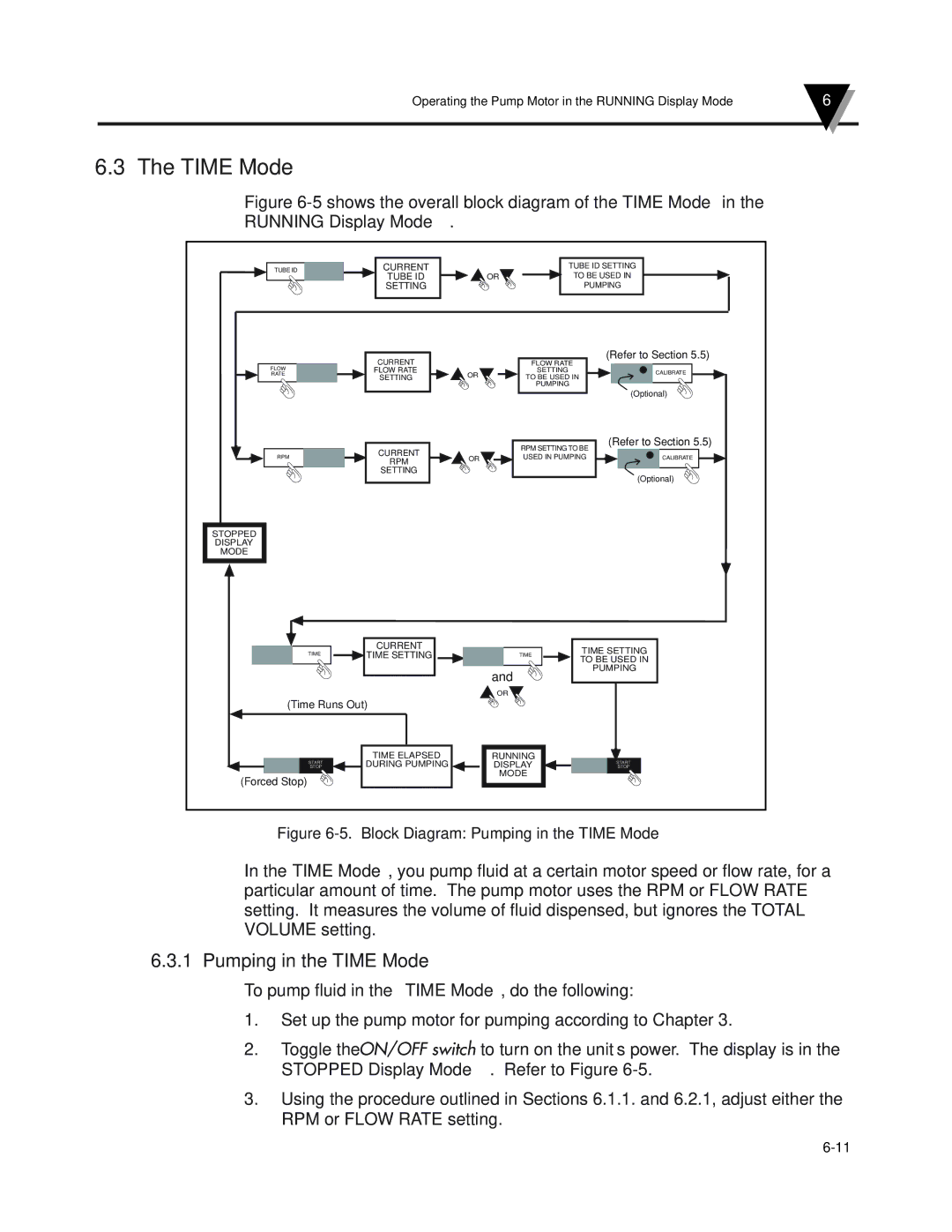
Figure 6-5 shows the overall block diagram of the TIME Mode in the
RUNNING Display Mode.
TUBE ID | CURRENT |
|
| TUBE ID SETTING | ||
| TUBE ID | OR |
| TO BE USED IN | ||
| SETTING |
|
| PUMPING | ||
| CURRENT |
| FLOW RATE | (Refer to Section 5.5) | ||
FLOW |
|
| ||||
FLOW RATE |
|
| SETTING | CALIBRATE | ||
RATE | SETTING | OR | TO BE USED IN | |||
|
| |||||
|
|
|
| PUMPING |
| |
|
|
|
|
| (Optional) | |
|
|
| RPM SETTING TO BE | (Refer to Section 5.5) | ||
| CURRENT |
|
| |||
RPM | OR | USED IN PUMPING | CALIBRATE | |||
RPM | ||||||
|
|
|
| |||
| SETTING |
|
|
| (Optional) | |
|
|
|
|
| ||
STOPPED |
|
|
|
|
| |
DISPLAY |
|
|
|
|
| |
MODE |
|
|
|
|
| |
| CURRENT |
|
| TIME SETTING | ||
TIME | TIME SETTING |
| TIME | |||
| TO BE USED IN | |||||
|
| and |
|
| PUMPING | |
|
|
|
|
| ||
|
| OR |
|
|
| |
(Time Runs Out) |
|
|
|
| ||
| TIME ELAPSED | RUNNING |
|
| ||
START | DURING PUMPING | DISPLAY |
| START | ||
STOP |
| STOP | ||||
(Forced Stop) |
| MODE |
|
| ||
|
|
|
|
| ||
Figure 6-5. Block Diagram: Pumping in the TIME Mode
In the TIME Mode, you pump fluid at a certain motor speed or flow rate, for a particular amount of time. The pump motor uses the RPM or FLOW RATE setting. It measures the volume of fluid dispensed, but ignores the TOTAL VOLUME setting.
6.3.1 Pumping in the TIME Mode
To pump fluid in the TIME Mode, do the following:
1.Set up the pump motor for pumping according to Chapter 3.
2.Toggle the ON/OFF switch to turn on the unit’s power. The display is in the STOPPED Display Mode. Refer to Figure
3.Using the procedure outlined in Sections 6.1.1. and 6.2.1, adjust either the RPM or FLOW RATE setting.
