Parts of the Pump Motor | 2 |
|
|
2.3 Right Side View
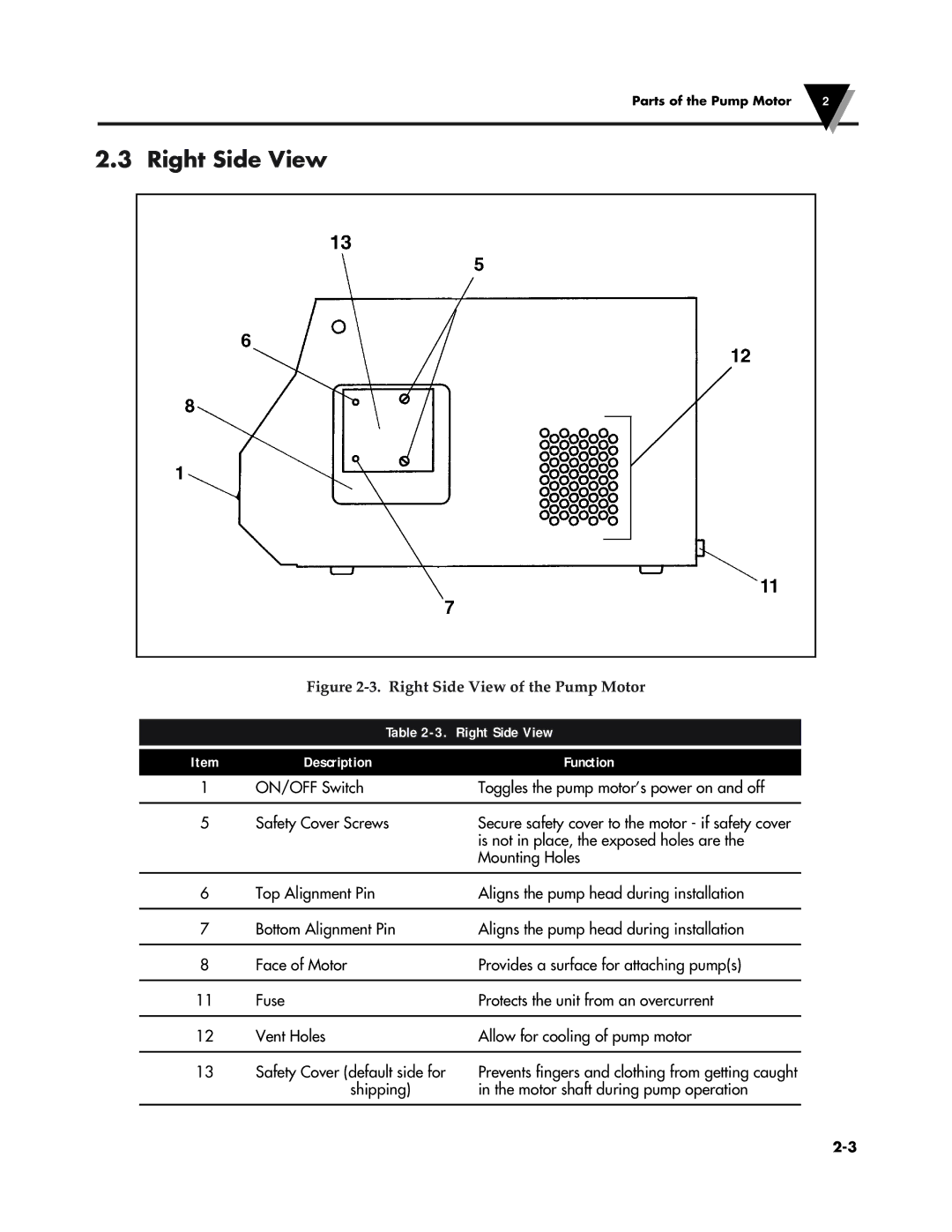
Figure 2-3. Right Side View of the Pump Motor
| Table | |
|
|
|
Item | Description | Function |
1 | ON/OFF Switch | Toggles the pump motor’s power on and off |
|
|
|
5 | Safety Cover Screws | Secure safety cover to the motor - if safety cover |
|
| is not in place, the exposed holes are the |
|
| Mounting Holes |
|
|
|
6 | Top Alignment Pin | Aligns the pump head during installation |
|
|
|
7 | Bottom Alignment Pin | Aligns the pump head during installation |
|
|
|
8 | Face of Motor | Provides a surface for attaching pump(s) |
|
|
|
11 | Fuse | Protects the unit from an overcurrent |
|
|
|
12 | Vent Holes | Allow for cooling of pump motor |
|
|
|
13Safety Cover (default side for shipping)
Prevents fingers and clothing from getting caught in the motor shaft during pump operation
