Connecting an A/B Switch
and a Signal Splitter
You can record a scrambled channel and watch an unscrambled one using a
Notes:
•This connection requires up to four addi- tional
•You cannot record scrambled channels without using a cable box.
•You can record a scrambled channel while you watch an unscrambled channel.
Cable Box
To TV’s
VHF/UHF
Terminals
|
| Out |
|
|
| |||||
| A/B Switch | |||||||||
|
|
|
|
|
|
|
|
|
| |
| A |
| B |
|
|
| ||||
|
| |||||||||
|
|
|
|
|
|
|
|
|
|
|
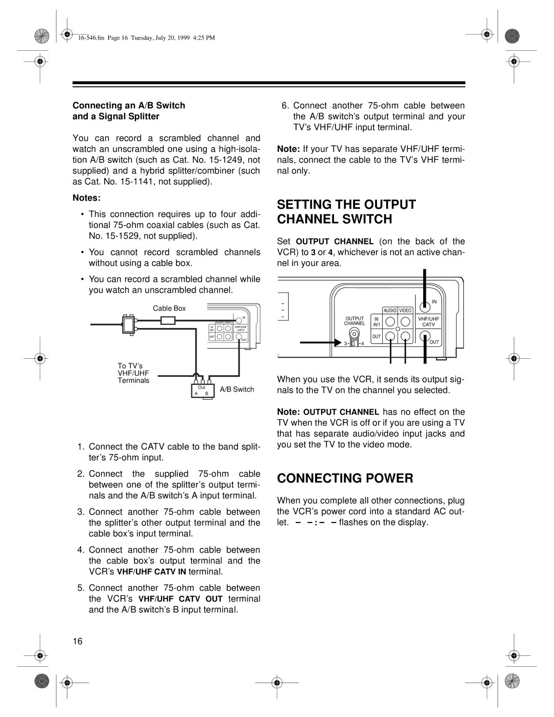
1.Connect the CATV cable to the band split- ter’s
2.Connect the supplied
3.Connect another
4.Connect another
5.Connect another
16
6.Connect another
Note: If your TV has separate VHF/UHF termi- nals, connect the cable to the TV’s VHF termi- nal only.
SETTING THE OUTPUT
CHANNEL SWITCH
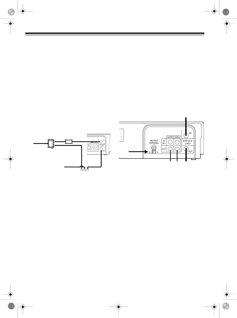
Set OUTPUT CHANNEL (on the back of the VCR) to 3 or 4, whichever is not an active chan- nel in your area.
When you use the VCR, it sends its output sig- nals to the TV on the channel you selected.
Note: OUTPUT CHANNEL has no effect on the TV when the VCR is off or if you are using a TV that has separate audio/video input jacks and you set the TV to the video mode.
CONNECTING POWER
When you complete all other connections, plug the VCR’s power cord into a standard AC out- let. –
