Cables and Pin Assignments
Power Input Connector
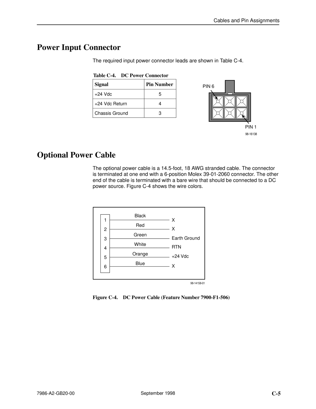
The required input power connector leads are shown in Table
Table C-4. DC Power Connector
Signal | Pin Number |
|
|
+24 Vdc | 5 |
|
|
+24 Vdc Return | 4 |
|
|
Chassis Ground | 3 |
|
|
PIN 6
PIN 1
Optional Power Cable
The optional power cable is a
|
|
| Black | X |
|
| 1 |
|
| ||
|
|
|
| ||
|
| Red | |||
| 2 |
| X |
| |
|
|
|
| ||
|
| Green | |||
| 3 |
| Earth Ground |
| |
|
|
|
| ||
|
| White | |||
| 4 |
| RTN |
| |
|
|
|
| ||
|
| Orange | |||
| 5 |
| +24 Vdc |
| |
|
|
|
| ||
|
| Blue | |||
| 6 |
| X |
| |
|
|
|
| ||
|
|
|
|
|
|
|
|
|
|
|
|
|
|
|
|
| |
Figure | DC Power Cable (Feature Number | ||||
September 1998 |
