About the Model 7986 Standalone Termination Unit
Network Configuration
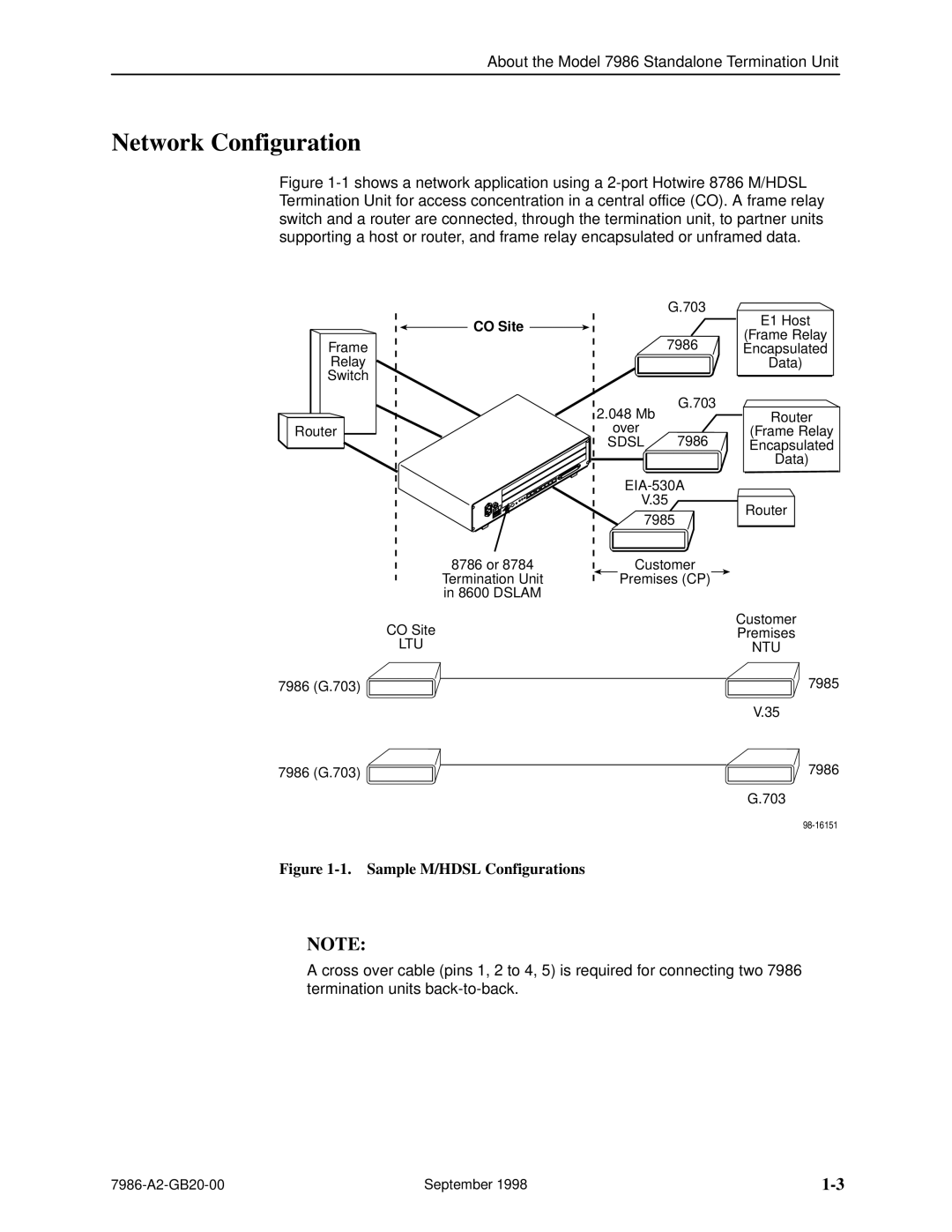
Figure 1-1 shows a network application using a 2-port Hotwire 8786 M/HDSL Termination Unit for access concentration in a central office (CO). A frame relay switch and a router are connected, through the termination unit, to partner units supporting a host or router, and frame relay encapsulated or unframed data.
Frame
Relay
Switch
Router
G.703
CO Site |
|
| 7986 |
2.048 Mb | G.703 |
| |
over | 7986 |
SDSL |
E1 Host
(Frame Relay
Encapsulated
Data)
Router
(Frame Relay
Encapsulated
Data)
V.35
7985
Router
8786 or 8784 |
| Customer |
Termination Unit |
| Premises (CP) |
in 8600 DSLAM |
|
|
|
|
CO Site
LTU
7986 (G.703) ![]()
7986 (G.703) ![]()
Customer
Premises
NTU
7985
V.35
7986
G.703
Figure 1-1. Sample M/HDSL Configurations
NOTE:
A cross over cable (pins 1, 2 to 4, 5) is required for connecting two 7986 termination units
September 1998 |