Manuals
/
Packard Bell
/
Computer Equipment
/
Laptop
Packard Bell
LJ65
manual
Remove the HDD from the carrier Chapter
Models:
LJ65
1
71
220
220
Download
220 pages
42.13 Kb
68
69
70
71
72
73
74
75
Specifications
System Block Diagram
Password
Indicators
Wireless Function Failure
Dimension
Savememoryconfig
Common Problems
Bios Setup Utility
Bios Flash Utilities
Page 71
Image 71
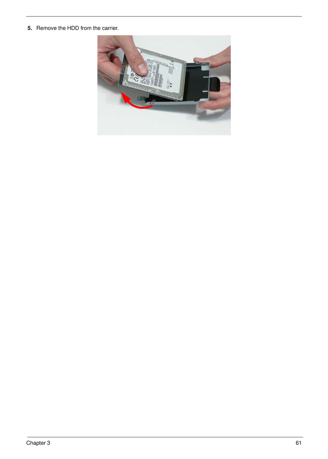
5.
Remove the HDD from the carrier.
Chapter 3
61
Page 70
Page 72
Page 71
Image 71
Page 70
Page 72
Contents
Packard Bell EasyNote LJ65 Service Guide
Revision History
III
Copyright
Conventions
Preface
Page
Table of Contents
Table of Contents
Model Definition and Configuration 190
Microsoft Windows Vista Environment Test
Chapter
Features
Audio
Dimensions and Weight
Storage subsystem
Optical Drive
Environment
Power subsystem
Special keys and controls
Interface
System Block Diagram
Component Icon Description
Your Notebook tour
Front View
Port Jack Reader
Left View
Rear View
Right View
Latch Hard drive bay Memory
Bottom View
Keyboard Area selected models
Indicators
Microphone Webcam
LCD Panel
Indicator Icon Description
Battery
Status Indicators
Function Left Button Right Button Main TouchPad
TouchPad Basics
Icon Key Type Description
Using the Keyboard
Key Types
Key Description
Windows Keys
Function Key Description
System Keys
Acer GridVista dual-display compatible
Using the System Utilities
CPU
Hardware Specifications and Configurations
Processor Specification
Processor Specifications
System Memory Specification
Northbridge Specification
Southbridge Specification
Memory Combinations Slot Total Memory
Graphics Controller Specification
LAN Interface Specification
Ddriii
Specifications
Wireless Module 802.11b/g Specification
Bluetooth Specification
Hard Disk Drive Interface Specification
WD1600BEVT
Hard Disk Drive Interface Specifications
8MB
RPM
Reading
Super-Multi Drive Module Specification
Writing
CD-ROM CD-RW
BluRay Combo Drive Module Specification
Write
Read
Panasonic AS-2007B
Battery Specification Cell
Sony AS-2007B/SIMPLO AS
LPL LP173WD1-TLA1
Audio Interface Specification
Lvds
Navigating the Bios Utility
Bios Setup Utility
Uuid
Information
Parameter Description
Parameter Description Format/Option
Main
Parameter Description Submenu Items
Advanced
URR
IGD-TV
Aspm
Aspm L1
Clear or Set
Disabled or
Security
Parameter Description Option
Removing a Password
Setting a Password
Continue
Changing a Password
Acpi S3
Power
Acpi S3
Emitm
DTS
USB Cdrom
Boot
Cmos
Exit
Bios Flash Utilities
DOS Flash Utility
Page
WinFlash Utility
UnlockHD
Remove HDD/BIOS Password Utilities
Remove HDD Password
Password
Cleaning Bios Passwords
Removing Bios Passwords
Using Boot Sequence Selector
Output
Using DMITools
Input
Using the LAN MAC Eeprom Utility
Chapter
Disassembly Requirements
Machine Disassembly and Replacement
Main Screw List Quantity Part Number
Pre-disassembly Instructions
Disassembly Process
General Information
Screw List Step Quantity
External Module Disassembly Process
External Modules Disassembly Flowchart
Removing the Battery Pack
Removing the SD dummy card
HDD1
Removing the Lower Covers
HDD2, Wlan
Step Size Quantity Screw Type ODD Module M2.5*5
Removing the Optical Drive Module
Step Size Quantity Screw Type ODD Bracket M2*3
Removing the Dimm Modules
Removing the Wlan Module
Step Size Quantity Screw Type Wlan Module M2*3
Step Size Quantity Screw Type HDD Carrier M3*3
Removing the Primary HDD Module
Remove the HDD from the carrier Chapter
Removing the Secondary HDD Module
Step Size Quantity Screw Type HDD Carrier M3*3
Main Unit Disassembly Flowchart
Main Unit Disassembly Process
Step Size Quantity Screw Type Switch Cover M2.5*5
Removing the Switch Cover
Chapter
Page
Removing the Media Board
Removing the Keyboard
Chapter
Step Size Quantity Screw Type LCD Module M2.5*8
Removing the LCD Module
Chapter
Page
Step Size Quantity Screw Type
Carefully remove the LCD module from the chassis Chapter
Removing the Upper Cover
Step Size Quantity Screw Type
Page
Page
Step Size Quantity Screw Type TouchPad Bracket M2*3
Removing the TouchPad Bracket
Removing the Media Board FFC
Removing the LED Board
Step Size Quantity Screw Type Speaker Module M2*3
Removing the Speaker Module
Lift the entire Speaker assembly clear of the Upper Cover
Removing the RTC Battery
Step Size Quantity Screw Type Modem Board M2*3
Removing the Modem Board
Page
Step Size Quantity Screw Type USB Board M2.5*5
Removing the USB Board
Page
Step Size Quantity Screw Type Mainboard M2.5*5
Removing the Mainboard
Removing the RJ-11 Jack
Chapter
Step Size Quantity Screw Type CPU Fan M2*3
Removing the CPU Fan
Step Size Quantity Screw Type Thermal Module M2.5*6.5
Removing the Thermal Module
Removing the CPU
LCD Module Disassembly Flowchart
LCD Module Disassembly Process
Removing the LCD Bezel
Removing the Camera Module
Step Size Quantity Screw Type LCD Panel M2.5*5
Removing the LCD Panel
Step Size Quantity Screw Type Power Board M2*3
Removing the Power Board
Removing the LCD Brackets and FPC Cable
Step Size Quantity Screw Type LCD Brackets M2*3
Removing the Microphone Module
Removing the Antennas
Page
Replacing the Antennas, Power Board, and MIC
LCD Module Reassembly Procedure
Page
108 Chapter
Replacing the LCD Panel
110 Chapter
Replacing the Camera Module
Replacing the LCD Bezel
Page
Replacing the Thermal Module
Main Module Reassembly Procedure
Replacing the CPU
Replacing the CPU Fan
Replacing the RJ-11 Jack
Replacing the Mainboard
Replacing the USB Board
Replacing the Modem Board
Replacing the Speaker Module
Replacing the Media Board FFC
Replacing the LED Board
Replacing the Upper Cover
Replacing the TouchPad Bracket
Reconnect the following cables as shown Chapter 123
124 Chapter
Page
Replacing the LCD Module
Page
128 Chapter
Replacing the Keyboard
Replacing the Media Board
Replacing the Switch Cover
132 Chapter
Replacing the Hard Disk Drive Modules
Replacing the Dimm Modules
Replacing the Wlan Module
Replacing the Lower Covers
Replacing the ODD Module
136 Chapter
Replacing the SD Dummy Card
Replacing the Battery
138 Chapter
Symptoms Verified Go To
Common Problems
SW/B
Power On Issue
Computer Shuts down Intermittently
No Post or Video
No Display Issue
Abnormal Video Display
Random Loss of Bios Settings
Built-In Keyboard Failure
LCD Failure
FFC
TouchPad Failure
Internal Speaker Failure
Sound Problems
146 Chapter
Internal Microphone Failure
Microphone Problems
Select Set up microphone
Select Startup Repair
HDD Not Operating Correctly
Select Repair your computer
ODD Not Operating Correctly
ODD Failure
Discs Do Not Play
Playback is Choppy
152 Chapter
USB/B
USB Right Side Failure
WiMax card
Wireless Function Failure
Re-assemble BT Cable
Bluetooth Function Test Failure
Easy Button Failure
External Mouse Failure
Thermal Unit Failure
Other Failures
Dimm
Intermittent Problems
Undetermined Problems
Motherboard Cmos Discharge
160 Chapter
Memory
Post Codes
Chipset Post Codes
Sec
BDS & Specific action
Code Description
Each Driver entry point used in 80PORT
Each Peim entry point used in 80PORT
Smbios
CF9RESET
Bootpriority
Fvbservice
Fwblockservice
Legacybios
Legacybiosplatform
Setuputility
Each SmmDriver entry point used in 80PORT
168 Chapter
Top View
JSATA1
PJP2
JMINI2
JSATA2
LS-5026P LED Board
LS-5022P USB Board
LS-5024P Cap Sensor Board
LED3
Power S/W
LS-5027P SW Board
Description Location
Clearing Password Check and Bios Recovery
Clearing Password Check
Steps for Clearing Bios Password Check
Steps for Bios Recovery by USB flash crisis disk
Bios Recovery by Crisis Disk
Bios Recovery Boot Block
Bios Recovery Hotkey
FRU Field Replaceable Unit List
Description Acer P/N
Packard Bell EasyNote LJ65 Exploded Diagrams
Main Assembly
Rear Assembly
LCD Assembly
Base Top Assembly
Category Description Acer Part Number
Packard Bell EasyNote LJ65 FRU List
Power Cord UK 3 PIN
Power Cord US 3 PIN
Power Cord EU 3 PIN
Power Cord AUS 3 PIN
HDD Door for NB W/ 2 HDD
Main HDD Door W/ Rubber Foot
HDD Carrier
ODD BD Combo Module
ODD SUPER-MULTI Drive Module
ODD BEZEL-SUPER Multi
ODD Bracket
Antenna AUX L
LCD Cover IMR-GTW
LCD Cover IMR-PB
Antenna Main R
Antenna *2, IMR, W/O CCD
Antenna Mimo R-3X3
Antenna *3, IMR, W/O CCD
LCD Bezel W/O Cmos
VGA Thermal MODULE-M92M
Battery Mylar
GM45 ICH9M LF
VGA Thermal MODULE-10PGE1
Screw M2.0D 3L K 5D NI
Screw List
Category Description
Screw M2D 4.0L K 4.6D NI NL
Chapter 189
Model Country Acer Part No Description
Appendix a
Packard Bell EasyNote LJ65 Series
Appendix a
Appendix a 192
Memory
Model
VGA Chip
Appendix a 194
Reader
Extra SW1 Card
Appendix a 196
NSM8XS NIS
Appendix a 198
Appendix B
Test Compatible Components
Microsoft Windows Vista Environment Test
2nd HDD
Vendor Type Description
Keyboard
Southbridge Chipset
WiFi Antenna
Modem
Northbridge Chipset
SP1x2MMW Lan Intel Wlan 512ANMMWG Shirley Peak MM#895361
Appendix C
Online Support Information
206
Index
208
209
210
Top
Page
Image
Contents