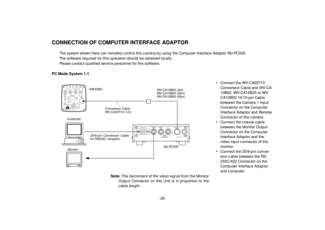
CONNECTION OF COMPUTER INTERFACE ADAPTOR
The system shown here can remotely control this camera by using the Computer Interface Adaptor
Please contact qualified service personnel for this software.
PC Mode System |
| ||||
PAGE | ITEM | UP | DOWN | IRIS |
|
| (AWC) | (ABC) | (BAR) |
| |
G/L IN |
| VIDEO OUT | |||
|
|
|
| ||
|
|
|
| ZOOM/FOCUS | |
VBS/HD | VD |
|
|
| |
75 ¶ | VIDEO/RGB |
|
| ||
ON |
|
|
|
| |
|
|
|
| REMOTE | |
OFF |
|
|
|
|
|
• Connect the |
Conversion Cable and |
10B02, |
CA10B50 |
CONTROL
CAUTION
![]() EXT DC IN SEE MANUAL
EXT DC IN SEE MANUAL
Computer
Monitor
Conversion Cable
MONITOR | CAMERA 2 | G/L IN | CAMERA 1 IN | ||
OUT | IN | ||||
|
|
| |||
|
| CAMERA SELECT | DC12V IN | ||
between the Camera 1 Input |
Connector on the Computer |
Interface Adaptor and Remote |
Connector of this camera. |
• Connect the coaxial cable |
between the Monitor Output |
Connector on the Computer |
Interface Adaptor and the |
video input connector of the |
monitor. |
• Connect the |
sion cable between the RS- |
232C/422 Connector on the |
Computer Interface Adaptor |
and computer. |
Note: The decrement of the video signal from the Monitor Output Connector on this Unit is in proportion to the cable length.