■CONNECTION OF DEVICE WITH AN RGB MONITOR OR AN IMAGE PROCESSOR
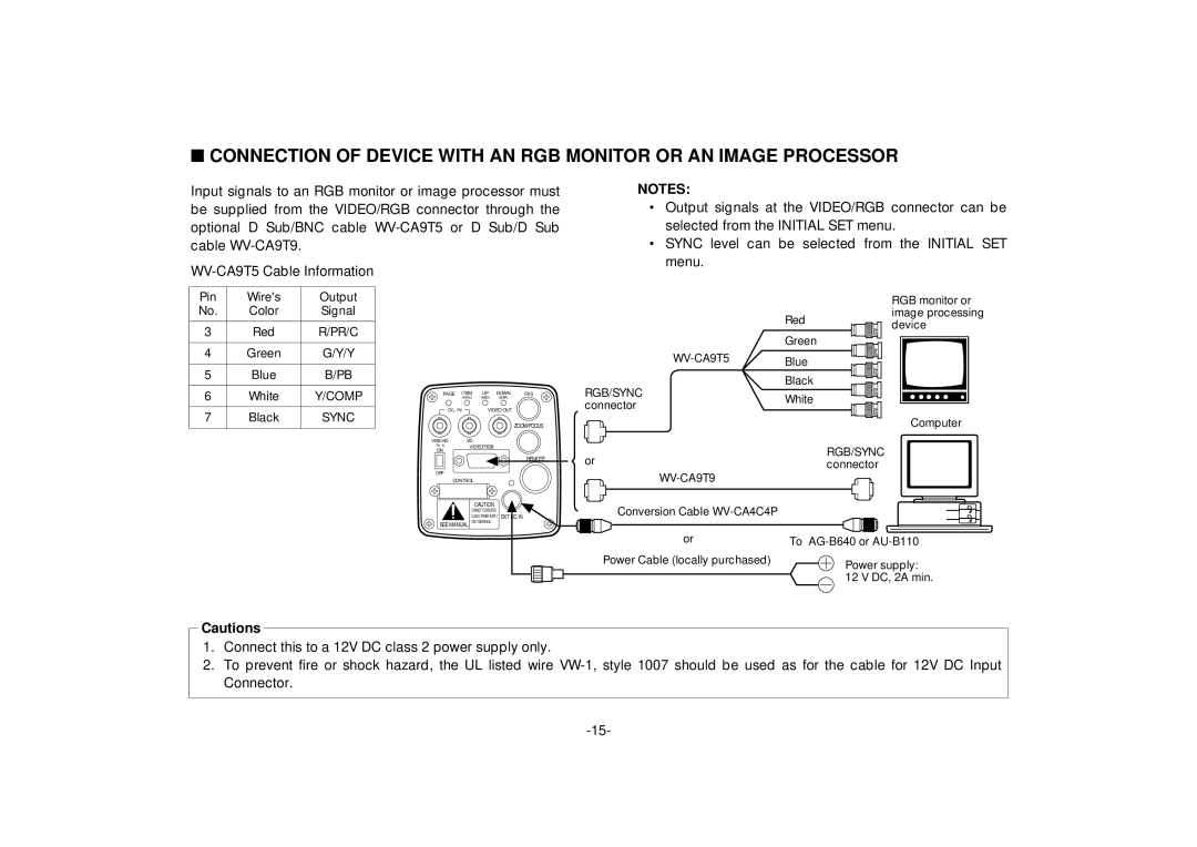
Input signals to an RGB monitor or image processor must be supplied from the VIDEO/RGB connector through the optional D Sub/BNC cable
Pin | Wire's | Output |
|
|
|
|
No. | Color | Signal |
|
|
|
|
3 | Red | R/PR/C |
|
|
|
|
4 | Green | G/Y/Y |
|
|
|
|
5 | Blue | B/PB |
|
|
|
|
6 | White | Y/COMP | PAGE | ITEM | UP | DOWN IRIS |
| (AWC) | (ABC) | (BAR) | |||
7 | Black | SYNC | G/L IN |
| VIDEO OUT | |
|
|
| ZOOM/FOCUS | |||
|
|
|
|
|
| |
|
|
| VBS/HD | VD |
|
|
|
|
| 75 ¶ | VIDEO/RGB |
| |
|
|
| ON |
|
|
|
REMOTE
OFF
CONTROL
CAUTION
CONNECT TO SPECIFIED
CLASS 2 POWER SUPPLY EXT DC IN
SEE MANUAL ONLY SEE MANUAL
NOTES:
•Output signals at the VIDEO/RGB connector can be selected from the INITIAL SET menu.
•SYNC level can be selected from the INITIAL SET menu.
|
| RGB monitor or |
| Red | image processing |
| device | |
|
| |
| Green |
|
Blue |
| |
|
| |
RGB/SYNC | Black |
|
White |
| |
connector |
| |
|
| |
|
| Computer |
or |
| RGB/SYNC |
| connector | |
|
| |
|
|
|
Conversion Cable |
|
|
or | To | |
Power Cable (locally purchased) |
| Power supply: |
|
| |
12 V DC, 2A min.
Cautions
1.Connect this to a 12V DC class 2 power supply only.
2.To prevent fire or shock hazard, the UL listed wire