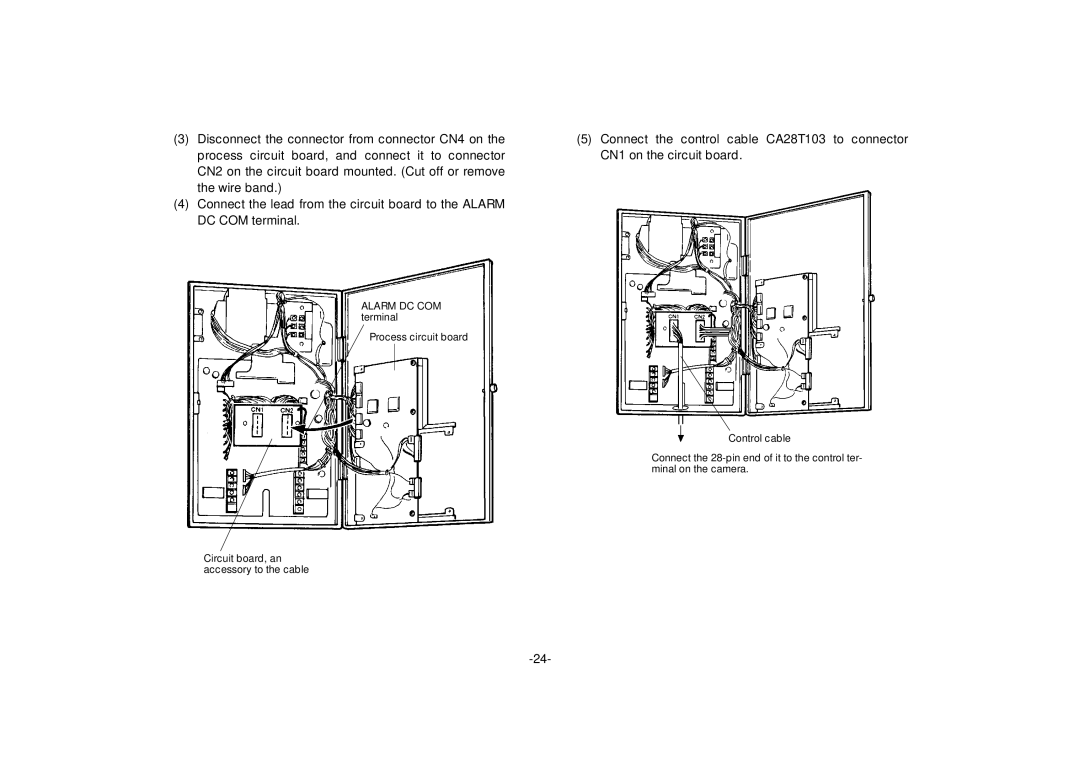
(3) | Disconnect the connector from connector CN4 on the | (5) Connect the control cable CA28T103 to connector |
| process circuit board, and connect it to connector | CN1 on the circuit board. |
| CN2 on the circuit board mounted. (Cut off or remove |
|
| the wire band.) |
|
(4) | Connect the lead from the circuit board to the ALARM |
|
| DC COM terminal. |
|
ALARM DC COM terminal
Process circuit board
Control cable
Connect the
Circuit board, an accessory to the cable