KX-P7100
3.9.Gear Support Bracket, Motor and Drive Gear Unit
Before handling, perform the following steps A - B :
A. Remove the Right Cover ( see Section 3.2 ).
B. Remove the Main Board Shield Cover ( see Section 3.7.1 ).
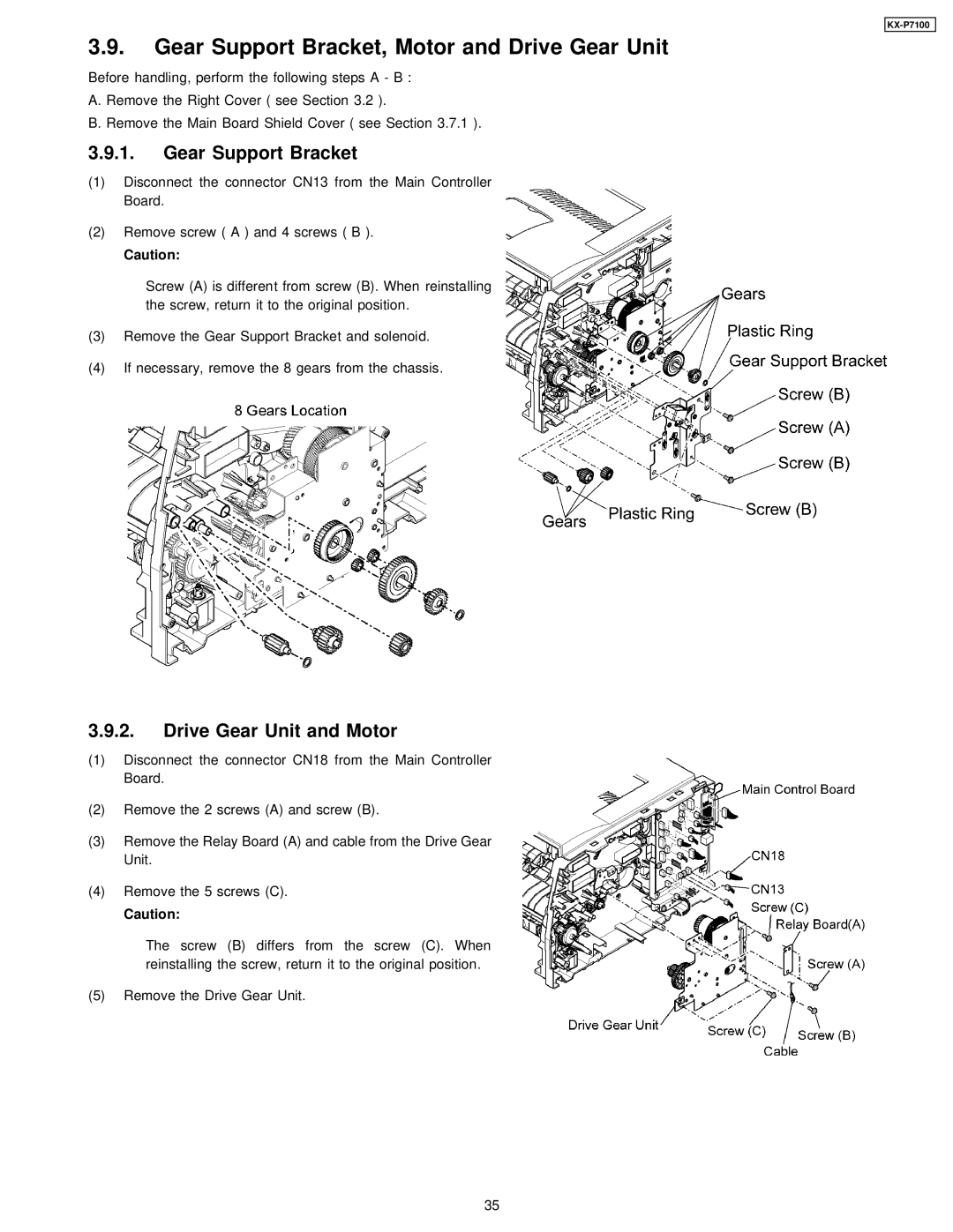
3.9.1.Gear Support Bracket
(1)Disconnect the connector CN13 from the Main Controller Board.
(2)Remove screw ( A ) and 4 screws ( B ).
Caution:
Screw (A) is different from screw (B). When reinstalling the screw, return it to the original position.
(3)Remove the Gear Support Bracket and solenoid.
(4)If necessary, remove the 8 gears from the chassis.
3.9.2.Drive Gear Unit and Motor
(1)Disconnect the connector CN18 from the Main Controller Board.
(2)Remove the 2 screws (A) and screw (B).
(3)Remove the Relay Board (A) and cable from the Drive Gear Unit.
(4)Remove the 5 screws (C).
Caution:
The screw (B) differs from the screw (C). When reinstalling the screw, return it to the original position.
(5)Remove the Drive Gear Unit.
35