KX-P7100
6 Explanation of Connectors
6.1.Main Board
6.1.1.CN1 ( to Front Panel )
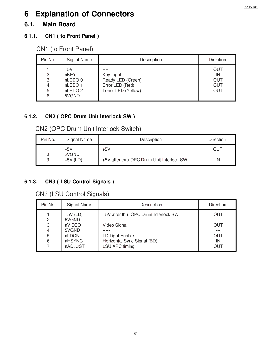
CN1 (to Front Panel)
Pin No. | Signal Name | Description | Direction |
|
|
|
|
1 | +5V | OUT | |
2 | nKEY | Key Input | IN |
3 | nLEDO 0 | Ready LED (Green) | OUT |
4 | nLEDO 1 | Error LED (Red) | OUT |
5 | nLEDO 2 | Toner LED (Yellow) | OUT |
6 | 5VGND |
| |
|
|
|
|
6.1.2.CN2 ( OPC Drum Unit Interlock SW )
CN2 (OPC Drum Unit Interlock Switch)
Pin No. | Signal Name | Description | Direction |
|
|
|
|
1 | +5V | +5V | OUT |
2 | 5VGND | ||
3 | +5V (LD) | +5V after thru OPC Drum Unit Interlock SW | IN |
|
|
|
|
6.1.3.CN3 ( LSU Control Signals )
CN3 (LSU Control Signals)
Pin No. | Signal Name | Description | Direction |
|
|
|
|
1 | +5V (LD) | +5V after thru OPC Drum Interlock SW | OUT |
2 | 5VGND | ||
3 | nVIDEO | Video Signal | OUT |
4 | 5VGND | ||
5 | nLDON | LD Light Enable | OUT |
6 | nHSYNC | Horizontal Sync Signal (BD) | IN |
7 | nADJUST | LSU APC timing | OUT |
|
|
|
|
81