Using the remote terminal
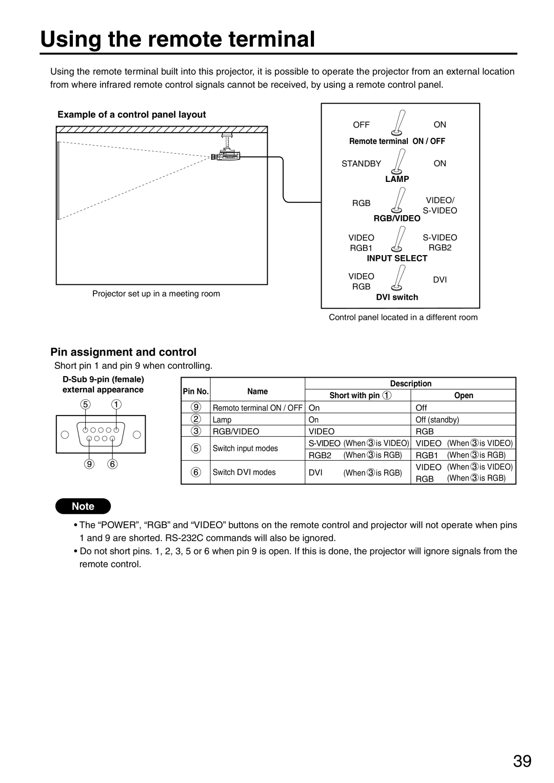
Using the remote terminal built into this projector, it is possible to operate the projector from an external location from where infrared remote control signals cannot be received, by using a remote control panel.
Example of a control panel layout
OFF | ON | |
Remote terminal ON / OFF | ||
STANDBY | ON | |
LAMP |
| |
RGB | VIDEO/ | |
RGB/VIDEO | ||
| ||
VIDEO | ||
RGB1 | RGB2 | |
| INPUT SELECT |
|
| VIDEO | DVI |
| RGB | |
Projector set up in a meeting room |
| |
DVI switch |
| |
|
| |
| Control panel located in a different room | |
Pin assignment and control
Short pin 1 and pin 9 when controlling.
Pin No. | Name |
|
| Description |
|
| |
Short with pin |
| Open |
| ||||
|
|
|
| ||||
| Remoto terminal ON / OFF | On |
|
| Off |
|
|
| Lamp | On |
|
| Off (standby) |
| |
| RGB/VIDEO | VIDEO |
|
| RGB |
|
|
| Switch input modes | is VIDEO) | VIDEO | (When | is VIDEO) | ||
| RGB2 | (When | is RGB) | RGB1 | (When | is RGB) | |
|
| ||||||
| Switch DVI modes | DVI | (When | is RGB) | VIDEO | (When | is VIDEO) |
| RGB | (When | is RGB) | ||||
|
|
|
|
| |||
Note
•The “POWER”, “RGB” and “VIDEO” buttons on the remote control and projector will not operate when pins 1 and 9 are shorted.
•Do not short pins. 1, 2, 3, 5 or 6 when pin 9 is open. If this is done, the projector will ignore signals from the remote control.
39
