Panasonic WJ-HD616K, WJ-HD716K manual Cascading connection of multiple recorders

Models: WJ-HD616K WJ-HD716K

1 156
Download 156 pages 35.47 Kb
Page 37
Image 37
Cascading connection of multiple recorders

Cascading connection of multiple recorders

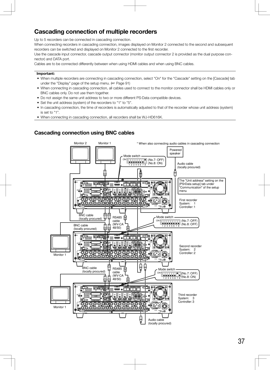
Up to 5 recorders can be connected in cascading connection.

When connecting recorders in cascading connection, images displayed on Monitor 2 connected to the second and subsequent recorders can be switched and displayed on Monitor 2 connected to the first recorder.

Use the cascade input connector, cascade output connector (monitor output connector 2 is provided as the dual purpose con- nector) and DATA port.

Cables are to be connected differently between when using HDMI cables and when using BNC cables.

Important:

When multiple recorders are connecting in cascading connection, select "On" for the "Cascade" setting on the [Cascade] tab under the "Display" page of the setup menu. (Page 91)

When connecting in cascading connection, all cables used to connect to the monitor connector shall be HDMI cables only or

BNC cables only. Do not use them together.

Do not assign the same unit address to two or more different PS·Data compatible devices.

Set the unit address (system) of the recorders to "1" to "5".

In cascading connection, the time of recorders is automatically adjusted to that of the recorder whose unit address (system) is set to "1".

When connecting in cascading connection, all recorders shall be WJ-HD616K.

Cascading connection using BNC cables

Monitor 2

Monitor 1

* When also connecting audio cables in cascading connection

Mode switch

Powered speaker


ON


(No.7: OFF)


1 2 3 4 5 6 7 8

(No.8: ON)

Audio cable


(locally procured)


EXT STORAGE


MODE


DATA

RS485(CAMERA)

10/100BASE-T


The "Unit address" setting on the


[PS·Data setup] tab under


3

2


1


123 4567 8


3

1


"Communication" of the setup


1


2

1


MONITOR


IN


menu


OUT


ALARM


2


2

1

2

1


CASCADE


OUT


ALARM/CONTROL

OUT-CASCADE-IN


CASCADE IN

OUT

MONITOR OUT(HD)

4

2

AUDIO


AUDIO IN

OUT


16

15

14

13

12

11

10

9

8

7

6

5

4

3

2

1

POWER

First recorder


IN


7


1

ON


System:

1


16

15

14

13

12

11

10

9

8

7

6

5

4

3

2

OUT

OFF


OUT


VIDEO


AC IN

SIGNAL

Controller: 1


GND


BNC cable


RS485


Mode switch


(locally procured)


(No.7: OFF)


cable


ON


BNC cable


(WV-CA


1 2 3 4 5 6 7 8 (No.8: OFF)


(locally procured)


48/50)


EXT STORAGE


MODE


DATA

RS485(CAMERA)

10/100BASE-T


3

2


1


123 4567 8


2

1


1


3

1


MONITOR


IN


OUT


ALARM


2


CASCADE


Second recorder


2

1

2

1


OUT


System:

2


ALARM/CONTROL

OUT-CASCADE-IN


CASCADE IN

OUT

MONITOR OUT(HD)

4

2

AUDIO


AUDIO IN

OUT


16

15

14

13

12

11

10

9

8

7

6

5

4

3

2

1

POWER

Controller: 2

Monitor 1

IN


7


ON


1

OFF


OUT


OUT


16

15

14

13

12

11

10

9

8

7

6

5

4

3

2


VIDEO


AC IN

SIGNAL


GND


BNC cable


RS485


Mode switch


(locally procured)


cable


ON

(No.7: OFF)


(WV-CA


1 2 3 4 5 6 7 8 (No.8: ON)


48/50)


EXT STORAGE


MODE


DATA

RS485(CAMERA)

10/100BASE-T


3

2


1


123 4567 8


2

1


ALARM


1


3

1

CASCADE


Third recorder


MONITOR


OUT


IN


System:

3


2


2

1

2

1


OUT


16

15

14

13

12

11

10

9

8

7

6

5

4

2

AUDIO

1

POWER

Controller: 3


4

3

2


ALARM/CONTROL

OUT-CASCADE-IN


CASCADE IN

OUT

MONITOR OUT(HD)

AUDIO IN

OUT


IN


ON


Monitor 1

OUT


7


1


OUT

OFF


16

15

14

13

12

11

10

9

8

7

6

5

4

3

2


VIDEO


AC IN

SIGNAL


GND


Audio cable (locally procured)

37

Page 37
Image 37
Panasonic WJ-HD616K, WJ-HD716K manual Cascading connection of multiple recorders, Cascading connection using BNC cables