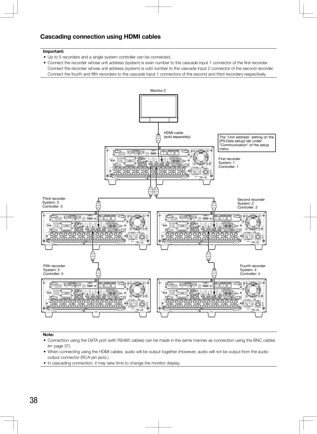
Cascading connection using HDMI cables

Important:

Up to 5 recorders and a single system controller can be connected.

Connect the recorder whose unit address (system) is even number to the cascade input 1 connector of the first recorder.

Connect the recorder whose unit address (system) is odd number to the cascade input 2 connector of the second recorder. Connect the fourth and fifth recorders to the cascade input 1 connectors of the second and third recorders respectively.

Monitor 2


HDMI cable


(sold separately)


The "Unit address" setting on the


[PS·Data setup] tab under


"Communication" of the setup


EXT STORAGE


MODE


DATA

RS485(CAMERA)

10/100BASE-T


menu


3


2


1

123 4567 8


2

1


First recorder


1


3

1


MONITOR


IN


OUT


ALARM


2


CASCADE


System: 1


2

1


2

1


OUT


Controller: 1

16

15

14

13

12

11

10

9

8

7

6

5

4

3

2

1

POWER


ALARM/CONTROL

OUT-CASCADE-IN

CASCADE IN

OUT MONITOR OUT(HD)

4

2

AUDIO


AUDIO IN

OUT


IN


ON


7


1


OUT


OUT


OFF


16

15

14

13

12

11

10

9

8

7

6

5

4

3

2


VIDEO


AC IN

SIGNAL


GND


Third recorder


Second recorder

System: 3


System: 2

Controller: 3


Controller: 2


EXT STORAGE


MODE


DATA

RS485(CAMERA)

10/100BASE-T


EXT STORAGE


MODE


DATA

RS485(CAMERA)

10/100BASE-T


3


2


1


123 4567 8


2

1


3


2


1


123 4567 8


2

1


1


3

1


1


3

1


MONITOR


IN


MONITOR


IN


OUT


OUT


ALARM


2


CASCADE


ALARM


2


CASCADE


2

1

2

1


OUT


2

1

2

1


OUT


ALARM/CONTROL

OUT-CASCADE-IN


CASCADE IN

OUT

MONITOR OUT(HD)

4

2

AUDIO


ALARM/CONTROL

OUT-CASCADE-IN


CASCADE IN

OUT

MONITOR OUT(HD)

4

2

AUDIO


AUDIO IN

OUT


AUDIO IN

OUT


16

15

14

13

12

11

10

9

8

7

6

5

4

3

2

1

POWER

16

15

14

13

12

11

10

9

8

7

6

5

4

3

2

1

POWER

IN


ON

IN


ON


7


7


1


1


OUT


OUT

OFF

OUT


OUT

OFF


16

15

14

13

12

11

10

9

8

7

6

5

4

3

2


16

15

14

13

12

11

10

9

8

7

6

5

4

3

2


VIDEO


AC IN

SIGNAL


VIDEO


AC IN

SIGNAL


GND


GND

Fifth recorder


Fourth recorder

System: 5


System: 4

Controller: 5


Controller: 4


EXT STORAGE


MODE


DATA

RS485(CAMERA)

10/100BASE-T


EXT STORAGE


MODE


DATA

RS485(CAMERA)

10/100BASE-T


3

2


1


123 4567 8


2

1


3


2


1


123 4567 8


2

1


1


3

1


1


3

1


MONITOR


IN


MONITOR


IN


OUT


OUT


ALARM


2


CASCADE


ALARM


2


CASCADE


2

1

2

1


OUT


2

1

2

1


OUT


ALARM/CONTROL

OUT-CASCADE-IN


CASCADE IN

OUT MONITOR OUT(HD)

4

2

AUDIO


ALARM/CONTROL

OUT-CASCADE-IN


CASCADE IN

OUT MONITOR OUT(HD)

4

2

AUDIO


AUDIO IN

OUT


AUDIO IN

OUT


16

15

14

13

12

11

10

9

8

7

6

5

4

3

2

1

POWER

16

15

14

13

12

11

10

9

8

7

6

5

4

3

2

1

POWER

IN


ON

IN


ON


7


7


1


1


OFF


OFF

OUT


OUT

OUT


OUT


16

15

14

13

12

11

10

9

8

7

6

5

4

3

2


16

15

14

13

12

11

10

9

8

7

6

5

4

3

2


VIDEO


AC IN

SIGNAL


VIDEO


AC IN

SIGNAL


GND


GND

Note:

Connection using the DATA port (with RS485 cables) can be made in the same manner as connection using the BNC cables

(+ page 37).

When connecting using the HDMI cables, audio will be output together (However, audio will not be output from the audio output connector (RCA pin jack).)

In cascading connection, it may take time to change the monitor display.

38

Page 38
Image 38
Panasonic WJ-HD716K, WJ-HD616K Cascading connection using Hdmi cables, Third recorder Second recorder System Controller

WJ-HD616K, WJ-HD716K specifications

The Panasonic WJ-HD716K and WJ-HD616K are advanced digital video recorders (DVRs) designed for professional surveillance applications. Both models offer high-quality recording, robust storage capabilities, and enhanced connectivity, making them suitable for a wide range of uses, from corporate security to residential monitoring.

The WJ-HD716K is distinguished by its ability to handle up to 16 channels of video input, while the WJ-HD616K supports up to 8 channels. This flexibility allows users to scale their surveillance systems according to their needs, whether they require comprehensive monitoring of a large facility or focused coverage in smaller environments.

One of the standout features of both models is their high-resolution recording capabilities. They support the recording of video in real-time at full D1 resolution (720 x 480 pixels), ensuring clear and detailed imagery. Additionally, the DVRs utilize advanced compression technologies such as MPEG-4, which optimize storage space without sacrificing video quality. This allows users to store significant amounts of footage while minimizing the need for extensive hard disk capacities.

The Panasonic WJ-HD716K and WJ-HD616K are equipped with sophisticated networking capabilities, including the ability to connect to various IP cameras. This makes them ideal for modern surveillance needs, as users can integrate them into existing IP networks easily. The models also feature remote monitoring capabilities through web browsers or dedicated mobile applications, allowing users to view live feeds, playback recorded footage, and manage settings from virtually anywhere.

In terms of user interface, both DVRs come with an intuitive graphical user interface that simplifies navigation and operation. Users can easily set recording schedules, configure system settings, and manage camera views through a clear and accessible on-screen menu.

Moreover, the reliability and durability of the WJ-HD716K and WJ-HD616K are noteworthy. The devices are designed to operate in demanding environments, ensuring consistent performance under various conditions. This reliability is further enhanced by features such as redundant storage options and robust backup capabilities, which protect against data loss.

In conclusion, the Panasonic WJ-HD716K and WJ-HD616K offer a compelling combination of features, technology, and reliability for modern surveillance systems. With their high-resolution recording, flexible connectivity options, and user-friendly interfaces, these DVRs represent a solid choice for anyone seeking to enhance their security infrastructure.