A. Command Line Interface
Interface and Service Domain IP Address Commands
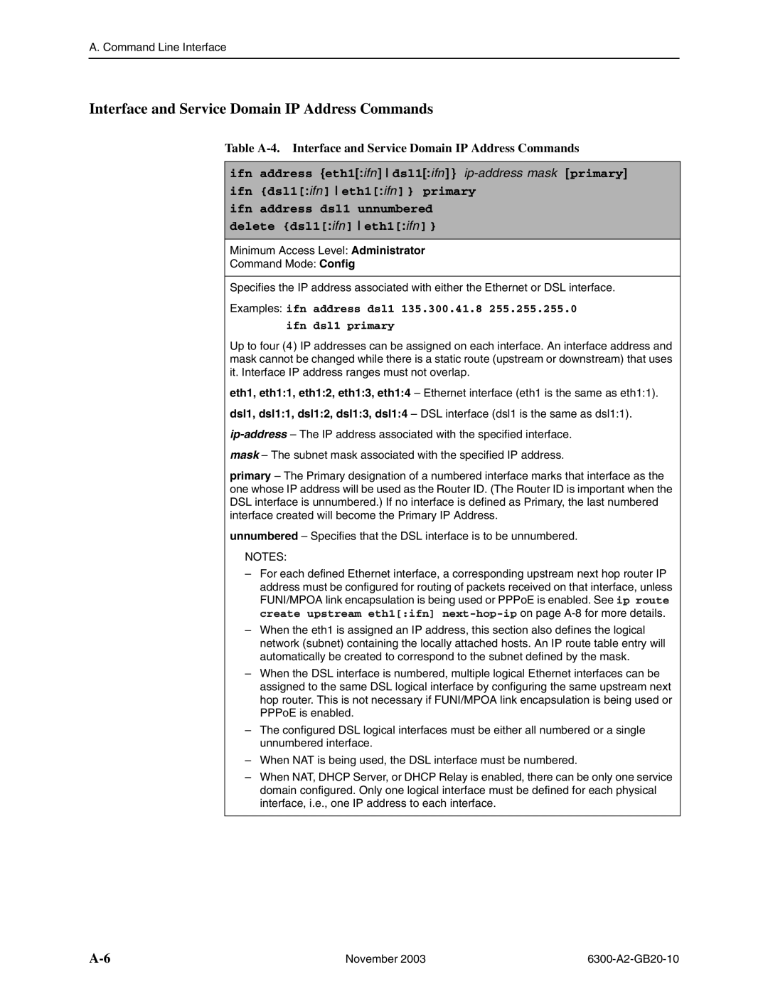
Table A-4. Interface and Service Domain IP Address Commands
ifn address {eth1[:ifn] dsl1[:ifn] }
ifn {dsl1[:ifn] eth1[:ifn] } primary
ifn address dsl1 unnumbered
delete {dsl1[:ifn] eth1[:ifn] }
Minimum Access Level: Administrator
Command Mode: Config
Specifies the IP address associated with either the Ethernet or DSL interface.
Examples: ifn address dsl1 135.300.41.8 255.255.255.0
ifn dsl1 primary
Up to four (4) IP addresses can be assigned on each interface. An interface address and mask cannot be changed while there is a static route (upstream or downstream) that uses it. Interface IP address ranges must not overlap.
eth1, eth1:1, eth1:2, eth1:3, eth1:4 – Ethernet interface (eth1 is the same as eth1:1).
dsl1, dsl1:1, dsl1:2, dsl1:3, dsl1:4 – DSL interface (dsl1 is the same as dsl1:1).
mask – The subnet mask associated with the specified IP address.
primary – The Primary designation of a numbered interface marks that interface as the one whose IP address will be used as the Router ID. (The Router ID is important when the DSL interface is unnumbered.) If no interface is defined as Primary, the last numbered interface created will become the Primary IP Address.
unnumbered – Specifies that the DSL interface is to be unnumbered.
NOTES:
–For each defined Ethernet interface, a corresponding upstream next hop router IP address must be configured for routing of packets received on that interface, unless FUNI/MPOA link encapsulation is being used or PPPoE is enabled. See ip route create upstream eth1[:ifn]
–When the eth1 is assigned an IP address, this section also defines the logical network (subnet) containing the locally attached hosts. An IP route table entry will automatically be created to correspond to the subnet defined by the mask.
–When the DSL interface is numbered, multiple logical Ethernet interfaces can be assigned to the same DSL logical interface by configuring the same upstream next hop router. This is not necessary if FUNI/MPOA link encapsulation is being used or PPPoE is enabled.
–The configured DSL logical interfaces must be either all numbered or a single unnumbered interface.
–When NAT is being used, the DSL interface must be numbered.
–When NAT, DHCP Server, or DHCP Relay is enabled, there can be only one service domain configured. Only one logical interface must be defined for each physical interface, i.e., one IP address to each interface.
November 2003 |