Model 3196RC | 5 • Troubleshooting and maintenance |
|
|
Introduction
This chapter describes troubleshooting and fault analysis that can be performed by the operator. If you require more help, refer to chapter 6, “Contacting Patton for assistance” on page 85. Refer to table 7 for a list of com- mon symptoms and suggested remedies.
Note The following information assumes that there is only one failure involving the Model 3196RC and that if you perform the corrective action listed, it will solve the problem. If you are unable to correct a failure, refer to chapter 6, “Contacting Patton for assistance” on page 85.
Note When removing the 3196RC from the chassis, follow the procedures
| cited in section |
Note When | |
| cedures cited in section |
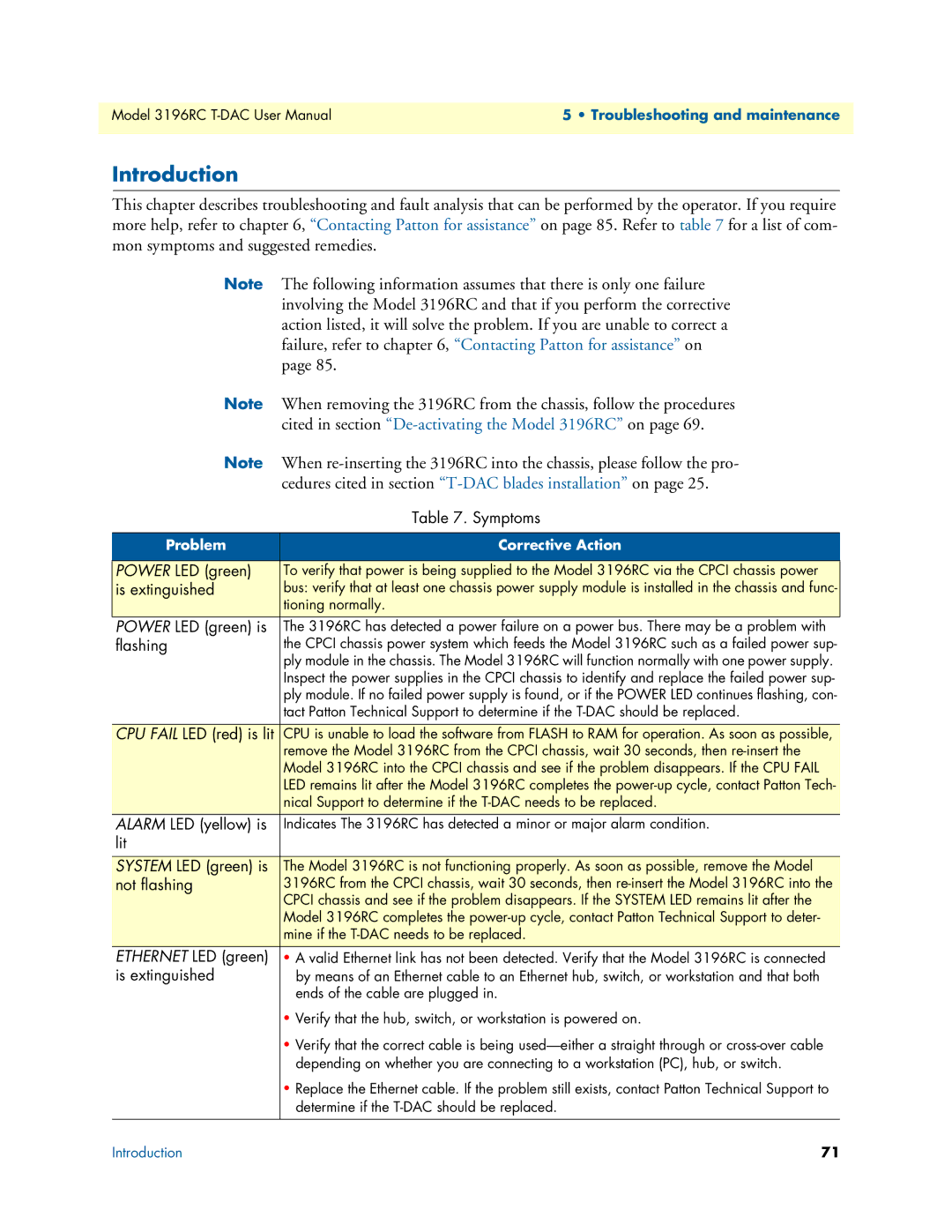
| Table 7. Symptoms |
|
|
Problem | Corrective Action |
|
|
POWER LED (green) | To verify that power is being supplied to the Model 3196RC via the CPCI chassis power |
is extinguished | bus: verify that at least one chassis power supply module is installed in the chassis and func- |
| tioning normally. |
POWER LED (green) is | The 3196RC has detected a power failure on a power bus. There may be a problem with |
flashing | the CPCI chassis power system which feeds the Model 3196RC such as a failed power sup- |
| ply module in the chassis. The Model 3196RC will function normally with one power supply. |
| Inspect the power supplies in the CPCI chassis to identify and replace the failed power sup- |
| ply module. If no failed power supply is found, or if the POWER LED continues flashing, con- |
| tact Patton Technical Support to determine if the |
|
|
CPU FAIL LED (red) is lit | CPU is unable to load the software from FLASH to RAM for operation. As soon as possible, |
| remove the Model 3196RC from the CPCI chassis, wait 30 seconds, then |
| Model 3196RC into the CPCI chassis and see if the problem disappears. If the CPU FAIL |
| LED remains lit after the Model 3196RC completes the |
| nical Support to determine if the |
ALARM LED (yellow) is | Indicates The 3196RC has detected a minor or major alarm condition. |
lit |
|
|
|
SYSTEM LED (green) is | The Model 3196RC is not functioning properly. As soon as possible, remove the Model |
not flashing | 3196RC from the CPCI chassis, wait 30 seconds, then |
| CPCI chassis and see if the problem disappears. If the SYSTEM LED remains lit after the |
| Model 3196RC completes the |
| mine if the |
ETHERNET LED (green) | • A valid Ethernet link has not been detected. Verify that the Model 3196RC is connected |
is extinguished | by means of an Ethernet cable to an Ethernet hub, switch, or workstation and that both |
| ends of the cable are plugged in. |
| • Verify that the hub, switch, or workstation is powered on. |
| • Verify that the correct cable is being |
| depending on whether you are connecting to a workstation (PC), hub, or switch. |
| • Replace the Ethernet cable. If the problem still exists, contact Patton Technical Support to |
| determine if the |
|
|
Introduction | 71 |