Model 3196RC
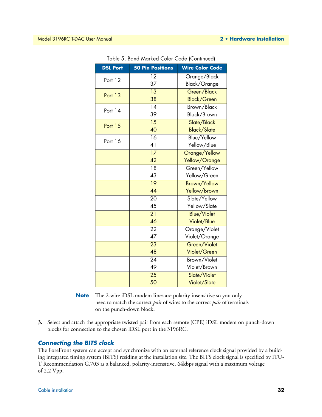
Table 5. Band Marked Color Code (Continued)
DSL Port | 50 Pin Positions | Wire Color Code | |
|
|
| |
Port 12 | 12 | Orange/Black | |
37 | Black/Orange | ||
| |||
|
|
| |
Port 13 | 13 | Green/Black | |
38 | Black/Green | ||
| |||
Port 14 | 14 | Brown/Black | |
39 | Black/Brown | ||
| |||
|
|
| |
Port 15 | 15 | Slate/Black | |
40 | Black/Slate | ||
| |||
Port 16 | 16 | Blue/Yellow | |
41 | Yellow/Blue | ||
| |||
|
|
| |
| 17 | Orange/Yellow | |
| 42 | Yellow/Orange | |
| 18 | Green/Yellow | |
| 43 | Yellow/Green | |
|
|
| |
| 19 | Brown/Yellow | |
| 44 | Yellow/Brown | |
| 20 | Slate/Yellow | |
| 45 | Yellow/Slate | |
|
|
| |
| 21 | Blue/Violet | |
| 46 | Violet/Blue | |
| 22 | Orange/Violet | |
| 47 | Violet/Orange | |
|
|
| |
| 23 | Green/Violet | |
| 48 | Violet/Green | |
| 24 | Brown/Violet | |
| 49 | Violet/Brown | |
|
|
| |
| 25 | Slate/Violet | |
| 50 | Violet/Slate | |
|
|
|
Note The
3.Select and attach the appropriate twisted pair from each remote (CPE) iDSL modem on
Connecting the BITS clock
The ForeFront system can accept and synchronize with an external reference clock signal provided by a build- ing integrated timing system (BITS) residing at the installation site. The BITS clock signal is specified by ITU- T Recommendation G.703 as a balanced,
of 2.2 Vpp.
Cable installation | 32 |