Model 3196RC | 5 • Troubleshooting and maintenance |
|
|
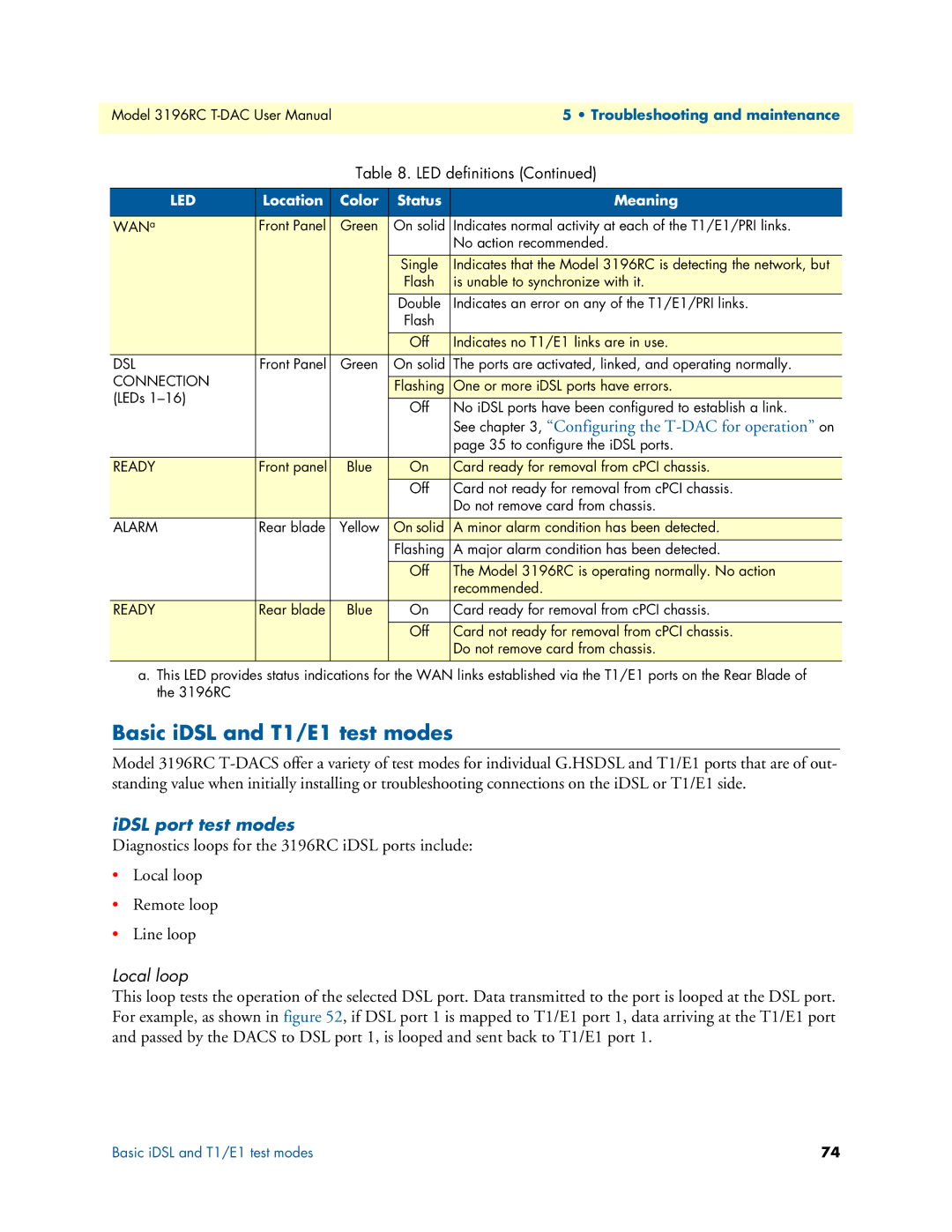
Table 8. LED definitions (Continued)
LED | Location | Color | Status | Meaning |
|
|
|
|
|
WANa | Front Panel | Green | On solid | Indicates normal activity at each of the T1/E1/PRI links. |
|
|
|
| No action recommended. |
|
|
|
|
|
|
|
| Single | Indicates that the Model 3196RC is detecting the network, but |
|
|
| Flash | is unable to synchronize with it. |
|
|
| Double | Indicates an error on any of the T1/E1/PRI links. |
|
|
| Flash |
|
|
|
|
|
|
|
|
| Off | Indicates no T1/E1 links are in use. |
DSL | Front Panel | Green | On solid | The ports are activated, linked, and operating normally. |
CONNECTION |
|
|
|
|
|
| Flashing | One or more iDSL ports have errors. | |
(LEDs |
|
| ||
|
| Off | No iDSL ports have been configured to establish a link. | |
|
|
| ||
|
|
|
| See chapter 3, “Configuring the |
|
|
|
| page 35 to configure the iDSL ports. |
|
|
|
|
|
READY | Front panel | Blue | On | Card ready for removal from cPCI chassis. |
|
|
| Off | Card not ready for removal from cPCI chassis. |
|
|
|
| Do not remove card from chassis. |
ALARM | Rear blade | Yellow | On solid | A minor alarm condition has been detected. |
|
|
| Flashing | A major alarm condition has been detected. |
|
|
|
|
|
|
|
| Off | The Model 3196RC is operating normally. No action |
|
|
|
| recommended. |
READY | Rear blade | Blue | On | Card ready for removal from cPCI chassis. |
|
|
|
|
|
|
|
| Off | Card not ready for removal from cPCI chassis. |
|
|
|
| Do not remove card from chassis. |
|
|
|
|
|
a.This LED provides status indications for the WAN links established via the T1/E1 ports on the Rear Blade of the 3196RC
Basic iDSL and T1/E1 test modes
Model 3196RC
iDSL port test modes
Diagnostics loops for the 3196RC iDSL ports include:
•Local loop
•Remote loop
•Line loop
Local loop
This loop tests the operation of the selected DSL port. Data transmitted to the port is looped at the DSL port. For example, as shown in figure 52, if DSL port 1 is mapped to T1/E1 port 1, data arriving at the T1/E1 port and passed by the DACS to DSL port 1, is looped and sent back to T1/E1 port 1.
Basic iDSL and T1/E1 test modes | 74 |