Contents
VCA mixing consoles
VCA block diagram
VCA Mono Input
Table of contents
Page
How to use this manual
Format
Conventions
Control Icons
Panel
Module Block diagram
1mono input module
Features
Mono input module
1mono input module
Gain
Module
Aux send features
Aux PRE switches 1-2
Aux 5-6 & 7-8 PRE switch
Aux sends 1-2
Module
VCA
EQ features
48TO24FITTED
High-pass filter-HPF
HPF-variable control
BAL Insert RTN Insert Send Direct OUT
Insert features
PRE-SOURC
Level meter features
Peak indicator-PK
Signal present indicator-SIG
Level meter
VCA Stereo Input Normally Fitted
Bus assignment features
Module Block diagram
Input fader
Solo switch
See Solo /VCA Edit switch section
Block diagram Module rear
Rear panel features
2stereo input module
+ Gain
Input signal switching
Line select Line 2 switch
Left and right mono-switches
Stereo input module
+ Gain
Input gain-GAIN
+ Gain AUX
Aux 1/2, 3/4 and 5-8 PRE switches
Aux sends 1-2, 3-4, 5-6
150
High-pass filter-HPF
HPF-High pass filter
Stereo Input
Metering features
Left and Right signal LED indicators
Peak indicator PK
Balance control
2stereo input module
Balance on-groups-BAL on
Solo
SIG
See Solo Features section
Line Bal Line
Line-input left and right 1/4TRS jacks
Balanced left and right line-in XLR connectors
Line-input left and right RCA connectors
3group module
VCA Masters 1 of 8 Shown
Group module features
Group module
Module Block diagram Panel
Shown
Post-group
Matrix sends
Matrix 1-4 levels-M1, M2, M3, M4
VCA Masters
Group dynamics section
Group BUS PAN
CompVOX on Switch
Comp Perc on Switch
Comp Auto on bothVOX and Perc switches depressed
Gate on downward expander
Output
Audio group control features
VCA
VCA group master control features
AUX
Meter bridge connector
Lamp dim
Master Groups Stereo inputs
Group output
Group insert point
Group insert send
Group insert return
4left / right & mono masters
Panel
Left / right & mono master modules
Matrix output control
Matrix master output level
Talk to
EXT
Matrix sends
Ster Module
Output EQ features
Left / right & mono masters
Matrix Balout
Output limiter features
Output limiter on switch
Output limiter threshold control
Gain reduction metering
Block diagram Panel
To Solo
Output features
Sum L/R switch Left / Right module
To Mono switch Mono module
Talk to L/R switch Left / Right module
4left / right & mono masters
Vca assign switch
Edit channel vca assign switch
Mono solo switches
100mm Left, Right and Mono faders
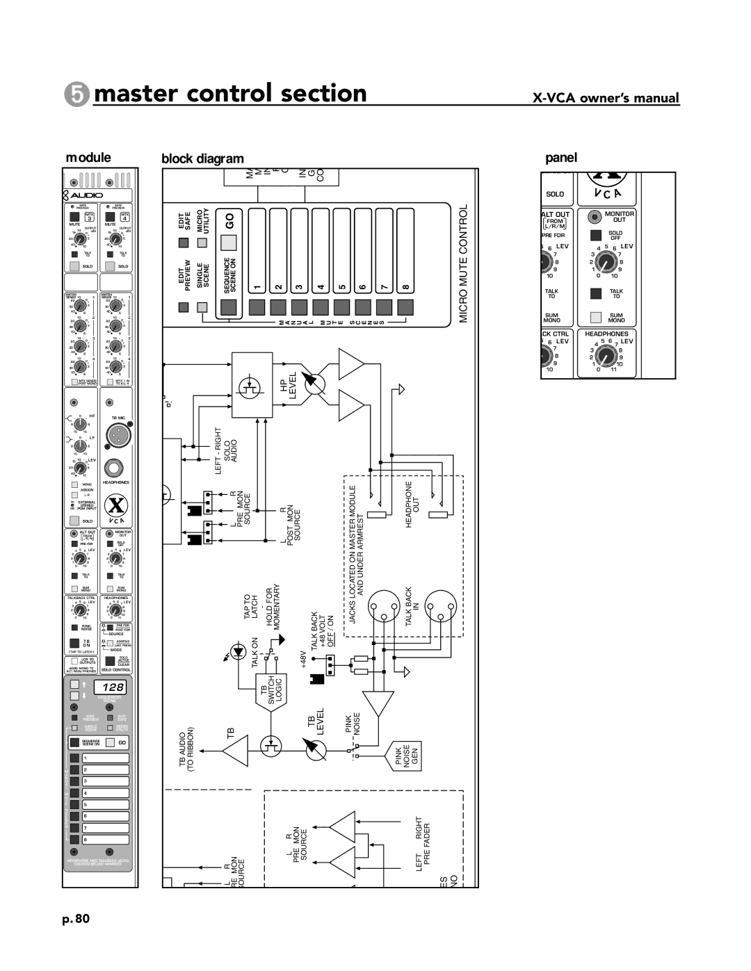
5master control section
Matrix Level
Master control section
Block diagram Panel
Matrix 1 in to all 4 switch
Matrix sends
Mono matrix 1-4 sends
Matrix sends post mono
4 Shown
External stereo program input
VCA MA
Alternate output features
Lower Area
Monitor output level control
Solo off switch
Monitor out
Control
Talkback and solo features
128
Solo features
Post fader switch
Additive / last press pressed switch
Solo active / clear switch
Midi Out
Matrix expansion connector
Matrix output connectors 1 through
Matrix external input connectors 1 through
Matrix expansion
VCA Master Module
Left, Right and Mono insert points
Stereo Program In jacks left and right
Left, Right and Mono master outputs
Monitor outputs left and right
128
Microprocessor control
Microprocessor controlled muting
Mute control panel Typical input or output
Mute controller
Microprocessor control
IRecall Next
Microprocessor control
KMute Switch
Channel mute controls
JStatus LED
LMute LED
Microprocessor control
Mute scenes
Creating a Mute Scene or Editing an existing one
Microprocessor control
Copying a mute scene
Copying a Mute Scene
Microprocessor control
Safe Scene
Microprocessor control
Display Meaning Settings
Utilities
Microprocessor control
Utility Mode
Changing and reviewing the utility changes
Vca facilities
Inputs and outputs Micro control panel
VCA operation overview
Vca facilities
Method 2- Master to Channel Assignment
VCA assigning overview
Method 1- Channel to Master Assignment
Vca facilities
VCA Assignment- Scene-to-Scene changes
Vca facilities
VCA assignment 1 detailed operation
This first method assigns Channels to Masters
Vca facilities
VCA Safe Mode
Vca facilities
VCA assignment 2 Detailed Operation
VCA Assignment- Masters to Channels
Vca facilities
VCA copy
Vca facilities
VCA Assignment starting fresh
Vca facilities
VCA Mute switch
Vca facilities
VCA Master Solo/Assign switch
Vca facilities
Channel initially un-solo’d, then 1VCA Group solo’d
VCA channel solo
Solo operation of a Channel assigned to multipleVCA Groups
Solo VCA edit switch
VCA Channel Assignment Function
Solo VCA edit switch
Solo Functions
Dynamics control
VCA dynamics control
Introduction
Dynamics control
To set up the compressor/limiter function
Group section Compressor/Limiter functions
Dynamics control
To set up the gate function
Group section gate functions
Dynamics control
Output limiter functions
Power supply
Model 5A power supply
Power supply0
Power supply usage
Console and power supply grounding
Redundant power supplies
Model 5A power supply Specifications
DC out receptacle DC out cable
Power requirements
Supply identification
Ground linking
Twin-supply operation
01/25/01

![]()
![]()
![]() 8
8