INSTALLATION
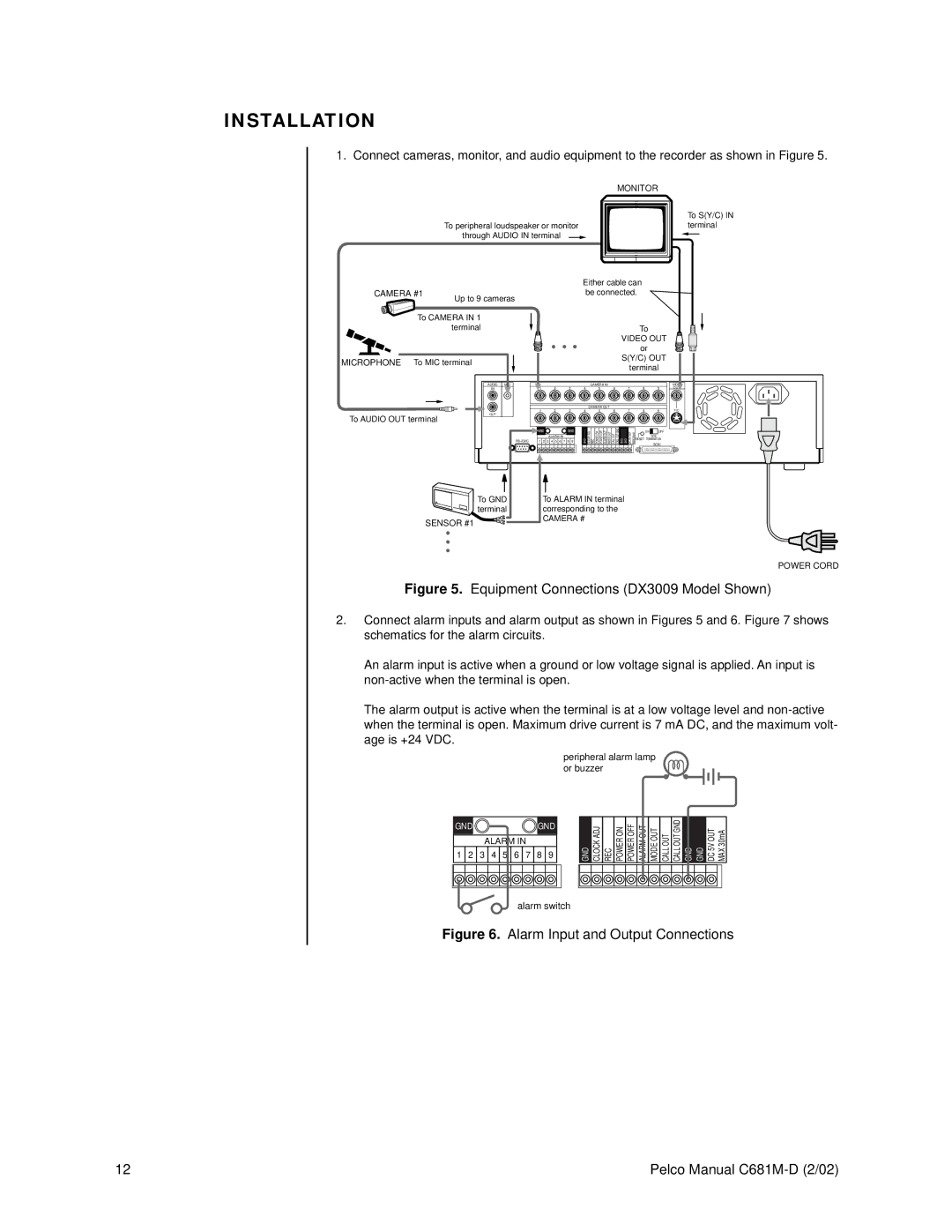
1. Connect cameras, monitor, and audio equipment to the recorder as shown in Figure 5.
| MONITOR |
| To S(Y/C) IN |
To peripheral loudspeaker or monitor | terminal |
through AUDIO IN terminal |
|
CAMERA #1
Up to 9 cameras
To CAMERA IN 1 terminal
MICROPHONE To MIC terminal
AUDIO MIC
IN
OUT
To AUDIO OUT terminal
Either cable can be connected.
To
VIDEO OUT
• • • or
S(Y/C) OUT
terminal
CAMERA IN
1 | 2 | 3 | 4 | 5 | 6 | 7 | 8 | 9 |
|
|
|
| CAMERA OUT |
|
|
|
|
1 | 2 | 3 | 4 | 5 | 6 | 7 | 8 | 9 |
VIDEO
OUT
Y/C
1 2 3 4 5 6 7 8 9 | GND | CLOCKADJ | REC | POWERON | POWEROFF | ALARMOUT | MODEOUT | OUTCALL | OUTCALLGND | GND | GND | 5VDCOUT | 30mAMAX |
|
| ||
| GND | GND |
|
|
|
|
|
|
|
|
|
|
|
|
| ON | OFF |
|
| ALARM IN |
|
|
|
|
|
|
|
|
|
|
|
| RESET |
| SCSI |
|
|
|
|
|
|
|
|
|
|
|
|
|
|
| TERMINATION | ||
|
|
|
|
|
|
|
|
|
|
|
|
|
|
|
|
| SCSI |
To GND | To ALARM IN terminal |
terminal | corresponding to the |
SENSOR #1 | CAMERA # |
|
•
•
•
POWER CORD
Figure 5. Equipment Connections (DX3009 Model Shown)
2.Connect alarm inputs and alarm output as shown in Figures 5 and 6. Figure 7 shows schematics for the alarm circuits.
An alarm input is active when a ground or low voltage signal is applied. An input is
The alarm output is active when the terminal is at a low voltage level and
peripheral alarm lamp or buzzer
GNDGND
ALARM IN
1 2 3 4 5 6 7 8 9
GND CLOCK ADJ
REC
POWER ON
POWER OFF
ALARM OUT
MODE OUT
CALL OUT
CALL OUT GND
GND GND
DC 5V OUT MAX 30mA
alarm switch
Figure 6. Alarm Input and Output Connections
12 | Pelco Manual |