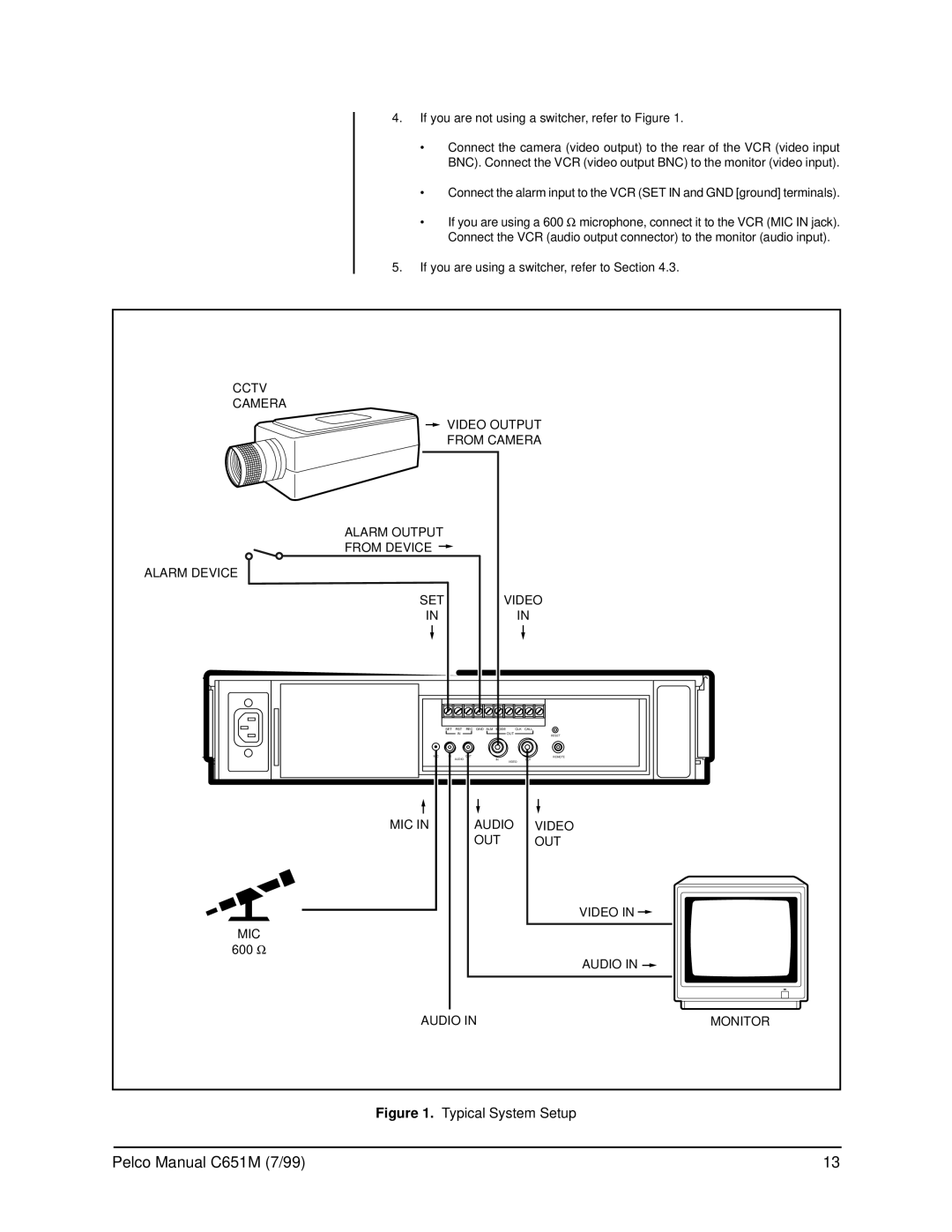
4.If you are not using a switcher, refer to Figure 1.
•Connect the camera (video output) to the rear of the VCR (video input BNC). Connect the VCR (video output BNC) to the monitor (video input).
•Connect the alarm input to the VCR (SET IN and GND [ground] terminals).
•If you are using a 600 Ω microphone, connect it to the VCR (MIC IN jack). Connect the VCR (audio output connector) to the monitor (audio input).
5.If you are using a switcher, refer to Section 4.3.
CCTV |
|
|
|
CAMERA |
|
|
|
| VIDEO OUTPUT | ||
| FROM CAMERA | ||
ALARM OUTPUT |
|
|
|
FROM DEVICE |
|
|
|
ALARM DEVICE |
|
|
|
SET |
| VIDEO | |
IN |
|
| IN |
| SET RST | REC GND ALM MODE | CLK CALL |
| IN | OUT | RESET |
|
|
| |
MIC | IN | OUT | REMOTE |
| AUDIO | IN | OUT |
|
| VIDEO | |
MIC IN |
| AUDIO | VIDEO |
|
| OUT | OUT |
|
|
| VIDEO IN |
MIC |
|
|
|
600 Ω |
|
|
|
|
|
| AUDIO IN |
AUDIO IN | MONITOR | ||
Figure 1. Typical System Setup
Pelco Manual C651M (7/99) | 13 |
