4.3 CONNECTING THE VCR TO A MULTIPLEXER
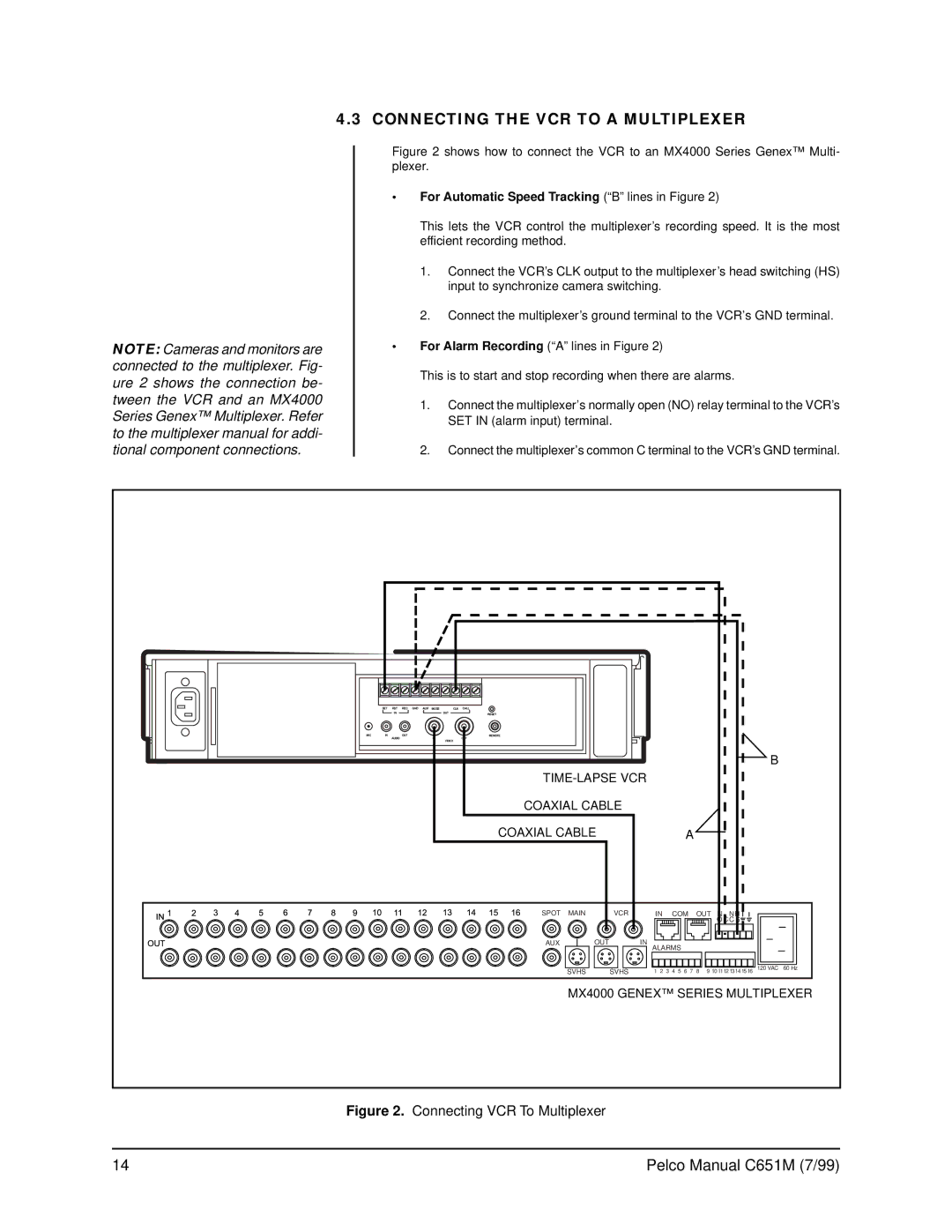
NOTE: Cameras and monitors are connected to the multiplexer. Fig- ure 2 shows the connection be- tween the VCR and an MX4000 Series Genex™ Multiplexer. Refer to the multiplexer manual for addi- tional component connections.
Figure 2 shows how to connect the VCR to an MX4000 Series Genex™ Multi- plexer.
•For Automatic Speed Tracking(“B” lines in Figure 2)
This lets the VCR control the multiplexer’s recording speed. It is the most efficient recording method.
1.Connect the VCR’s CLK output to the multiplexer’s head switching (HS) input to synchronize camera switching.
2.Connect the multiplexer’s ground terminal to the VCR’s GND terminal.
•For Alarm Recording(“A” lines in Figure 2)
This is to start and stop recording when there are alarms.
1.Connect the multiplexer’s normally open (NO) relay terminal to the VCR’s SET IN (alarm input) terminal.
2.Connect the multiplexer’s common C terminal to the VCR’s GND terminal.
| SET | RST | REC GND ALM MODE |
| CLK CALL |
|
|
|
|
|
|
|
|
|
|
| IN |
| OUT | RESET |
|
|
|
|
|
|
|
|
|
MIC | IN |
| OUT |
| REMOTE |
|
|
|
|
|
|
|
|
|
|
| AUDIO | IN | VIDEO | OUT |
|
|
|
|
|
|
|
|
|
|
|
|
|
|
|
|
|
|
|
|
|
|
| |
|
|
|
|
|
|
|
|
|
|
|
|
| B |
|
|
|
|
|
|
|
|
|
|
|
|
| |||
|
|
|
|
| COAXIAL CABLE |
|
|
|
|
|
|
| ||
|
|
|
|
| COAXIAL CABLE |
|
| A |
|
|
|
| ||
|
|
|
|
| SPOT | MAIN | VCR | IN | COM | OUT | N NH |
|
| |
|
|
|
|
|
|
|
|
|
|
|
| OC C S |
|
|
|
|
|
|
| AUX |
| OUT | IN |
|
|
|
|
|
|
|
|
|
|
|
|
|
| ALARMS |
|
|
|
|
| |
|
|
|
|
|
| SVHS | SVHS | 1 2 | 3 4 5 | 6 7 | 8 9 10 1112 1314 15 16 | 120 VAC | 60 Hz | |
MX4000 GENEX™ SERIES MULTIPLEXER
Figure 2. Connecting VCR To Multiplexer
14 | Pelco Manual C651M (7/99) |
