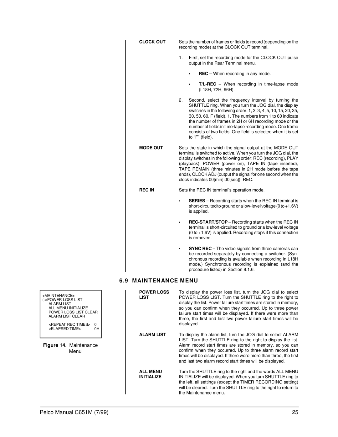
<MAINTENANCE> )POWER LOSS LIST
ALARM LIST
ALL MENU INITIALIZE POWER LOSS LIST CLEAR ALARM LIST CLEAR
<REPEAT REC TIMES> | 0 |
<ELAPSED TIME> | 0H |
Figure 14. Maintenance Menu
CLOCK OUT | Sets the number of frames or fields to record (depending on the |
| recording mode) at the CLOCK OUT terminal. |
| 1. First, set the recording mode for the CLOCK OUT pulse |
| output in the Rear Terminal menu. |
| • REC– When recording in any mode. |
| • |
| (L18H, 72H, 96H). |
| 2. Second, select the frequency interval by turning the |
| SHUTTLE ring. When you turn the JOG dial, the display |
| switches in the following order: 1, 2, 3, 4, 5, 10, 15, 20, 25, |
| 30, 50, 60, F (field), 1. The numbers from 1 to 60 indicate |
| the number of frames in 2H or 6H recording mode or the |
| number of fields in |
| consists of two fields. One field is selected when it is set |
| to “F” (field). |
MODE OUT | Sets the state in which the signal output at the MODE OUT |
| terminal is switched to active. When you turn the JOG dial, the |
| display switches in the following order: REC (recording), PLAY |
| (playback), POWER (power on), TAPE IN (tape inserted), |
| TAPE REMAIN (three minutes in 2H mode before the tape |
| ends), CLOCK ADJ (output the signal for one second when the |
| clock indicates 00[min]:00[sec]), REC. |
REC IN | Sets the REC IN terminal’s operation mode. |
•SERIES– Recording starts when the REC IN terminal is
•
•SYNC REC– The video signals from three cameras can be recorded separately by connecting a switcher. (Syn- chronous recording is available when recording in L18H mode.) Synchronous recording is explained (and the procedure listed) in Section 8.1.6.
6.9MAINTENANCE MENU
POWER LOSS | To display the power loss list, turn the JOG dial to select |
LIST | POWER LOSS LIST. Turn the SHUTTLE ring to the right to |
| display the list. Power failure start times are stored in memory, |
| so you can confirm when they occurred. Up to three power |
| failure start times will be displayed. If there were more than |
| three, the first and last two power failure start times will be |
| displayed. |
ALARM LIST | To display the alarm list, turn the JOG dial to select ALARM |
| LIST. Turn the SHUTTLE ring to the right to display the list. |
| Alarm record start times are stored in memory, so you can |
| confirm when they occurred. Up to three alarm record start |
| times will be displayed. If there were more than three, the first |
| and last two alarm record start times will be displayed. |
ALL MENU | Turn the SHUTTLE ring to the right and the words ALL MENU |
INITIALIZE | INITIALIZE will be displayed. When you turn SHUTTLE ring to |
| the left, all settings (except the TIMER RECORDING setting) |
| will be cleared. Turn the SHUTTLE ring to the right to return to |
| the Maintenance menu. |
Pelco Manual C651M (7/99) | 25 |