PDP-607XD PDP-507XD PDP-427XD
Page
English
STANDBY/ON Indicator
STANDBY/ON Button
Contents
Contents
Using the Teletext Functions
Appendix
Usage guidelines
Installation guidelines
Important User Guidance Information
Do not display Teletext for a prolonged period of time
Plasma Television protection function
When not using the product for a long period of time
Cleaning the cabinet
Information of pixel defect
Panel sticking and after-image lag
Preventing damage from screen burning
Safety Precautions
Rear view PDP-607XD Side view
Installation Precautions
When using other items
Rear view PDP-507XD
Cleaning cloth Ferrite core
Supplied Accessories
Power cord 2 m For Europe, except UK For UK and Eire
Remote control unit AA size battery x
Plasma Television
Front view PDP-607XD Power button
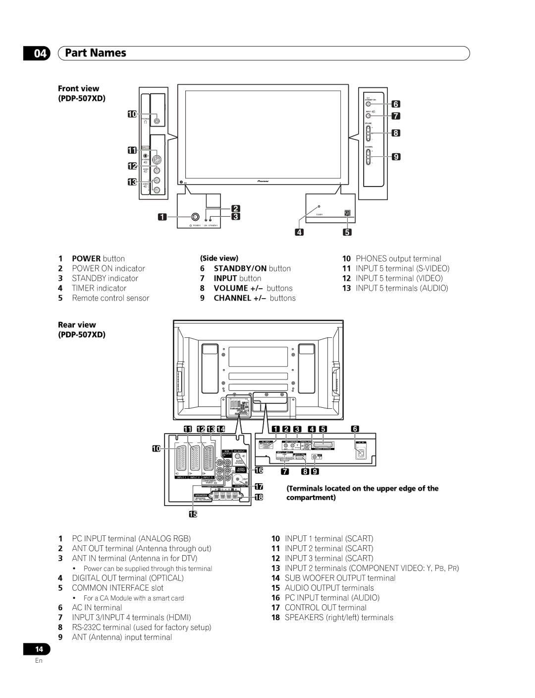
Part Names
PC Input terminal Audio
Phones output terminal
Power on indicator STANDBY/ON button
Front view PDP-507XD
Input 5 terminal S-VIDEO
Compartment
Front view PDP-427XD
Terminals located on the upper edge
ANT in terminal Antenna in for DTV
Remote control unit
Moving the Plasma Television
Installing the Plasma Television
Preparation
Stabilizing on a table or floor
Preventing the Plasma Television from Falling Over
PDP-507XD
Mm min
Plasma Television rear view Attaching the ferrite core
Connecting the power cord
Routing cables
Attaching and removing speed clamps
Connecting to an antenna
Attaching speed clamps to the main unit
Antenna cable commercially available
Open the battery cover
Preparing the remote control unit
Allowed operation range of the remote control unit
Inserting batteries
Watching TV
Turning on/off the power
Plasma Television status indicators
PDP-427XD
Using 0 to 9 on the remote control unit
Switching between the TV and DTV modes
Using P +/P on the remote control unit
Changing channels
Using i+/i- on the remote control unit
Tuning to your favourite analogue channels
Changing the volume and sound
Using eon the remote control unit
Using g on the remote control unit
Each time you press g, MTS toggles as shown below
Splitting the screen
Press cto select the display mode
Use the multiscreen functions
Screen Main screen
Freezing images
Normal image
AV mode menus
Menu Setup
Using the menu
PC mode menus
Setting up analogue TV channels manually
Basic Adjustment Settings
Setting up TV channels automatically
Using Auto Installation
Selecting a decoder input terminal
Setting Child Lock
Reducing video noise
Select Store Select Yes, Yes Listed, or No
Labeling TV channels
Language setting
Sorting preset TV channels
For AV source
Basic picture adjustments
AV Selection
For PC source
Using Colour Temp
Advanced picture adjustments
Using PureCinema
Using CTI
Using Intelligent Colour
Using Colour Management
Using Colour Space
Eliminating noise from images
Using the Dynamic Range Expander DRE functions
Using the 3DYC and I-P Mode
Sound adjustments
Front Surround
No Signal off AV mode only
Listening to audio from the sub screen using headphones
Power Control
Select Sub Volume Select the desired volume level
No Operation off AV mode only
Power Management PC mode only
Changing channels
Enjoying DTV broadcasts
Watching DTV programmes
Viewing a channel banner
Replacing the existing channels
Reconfiguring the DTV channel settings
Reselecting a country
Adding new channels
Switching on/off the power to the antenna
Checking signal strength
Restoring the system defaults
Activating the Favourites function
Customizing channel related settings
Setting Channel Options
Activating the Auto Skip
Selecting a digital audio format
Setting the Child Lock
Sorting preset DTV channels
Select an age limit You can select 4 to 18, and Off
Setting Update Time
Using Software Update
Using Auto Update
Starting Manual Update
Screen Saver
Common Interface
Programme information
Using the Electronic Programme Guide EPGfor DTV only
EPG display format
General programme list
Using the EPG
You can modify the presettings here / , / then
Presetting TV programmes using
Using auto channel select and standby recording
Setting the timer manually
Priority rules for overlapped presettings
Using the EPG
Changing/cancelling TV programme presettings
Changing priorities for overlapped presettings
Using the menu
Select Date
Using other useful EPG functions
EPG Jump
Select Time
Adjusting image positions AV mode only
Useful Adjustment Settings
Switching the vertical drive frequency AV mode only
Adjusting image positions and clock manually PC mode only
Television to select an input source
Selecting an input signal type
Colour system setting AV mode only
PC mode for XGA signals
AV mode
PC mode except for XGA signals
PC mode except for XGA signals Dot by Dot
Selecting a screen size for received 43 aspect ratio signals
Selecting a screen size automatically
Entering a password
Sleep Timer
Using a password AV mode only
Changing the password
If you forget the password
Resetting the password function
Disabling the password function
Watching a VCR image
Enjoying through External Equipment
Watching a decoder image
To specify the type of digital video signals
Using Hdmi Input
Connecting Hdmi equipment
Hdmi equipment
Using i/o link.A
Watching a DVD image
Using the Scart output function
Connecting a DVD player
Displaying a DVD image
Enjoying a game console or watching camcorder images
Switching the Scart output
Connecting a game console or camcorder
Displaying an image from the game console or camcorder
Watching an image from a personal computer
Enjoying through audio equipment in connection
When SR+ is used Use the SR+ cable available as option
Connecting control cords
Presetting manufacture codes
About SR+
Manufacture codes
STB
Source a
STB set top box control buttons
+/P
Disc Navi DVD/HDD recorder DVR only
+/P DVD/HDD recorder DVR only
REC DVD/HDD recorder DVR only
Stop
Press to select channels of the TV tuner on the VCR
Turns the power of the VCR on and off
VCR control buttons
Erec
Operating the Teletext basics
Using the Teletext Functions
What is Teletext?
Turning on and off Teletext
Displaying TOP Over View
Displaying subpages
Selecting and operating Teletext pages
Displaying subtitle pages
Appendix
Troubleshooting
Problem Possible Solution
Code Message Check
Pin No Signal name
Connecting pin assignments for Scart
Signal names for 15-pin mini D-sub connecter Front view
Specifications
Control OUT
Trademarks
English Français
Touche STANDBY/ON
Témoin STANDBY/ON
Table des matières
11 Réglages utiles
Utilisation du guide électronique de
Programme EPG pour DTV uniquement
Emploi d’un appareil extérieur
Utilisation des fonctions télétexte
Annexe
Instructions d’usage
Instructions d’installation
Informations importantes pour l’utilisateur
Information sur les défauts de pixel
Ne collez aucune étiquette ni aucun ruban sur l’appareil
Fonction de protection du téléviseur à plasma
Rayonnement infrarouge
Rémanence d’image sur le panneau
Prévention des dommages des brûlures d’écran
02 Précautions de sécurité
Précautions de sécurité
Cordon d’alimentation 2 m
Accessoires fournis
Boîtier de télécommande Pile AA x
Pour l’Eire et le
Témoin Timer Touches Volume +
Touche Power
Témoin Power on Touche STANDBY/ON
Nomenclature
Vue de face PDP-507XD
Capteur de télécommande Touches Channel +
Vue de face PDP-427XD
Boîtier de télécommande
Touches de couleur ROUGE, VERT, JAUNE, Bleu
Préparation
Installation du téléviseur à plasma
Déplacement du téléviseur à plasma
Fixation sur une table ou au sol
05 Préparation
Pour empêcher le téléviseur à plasma de se renverser
Téléviseur à plasma vue de dos Fixation du noyau de ferrite
Connexion du cordon d’alimentation
Cheminement des câbles
Pose et dépose des colliers rapides
Connexion à une antenne
Fixation des colliers rapides à l’appareil
Câble d’antenne disponible dans le commerce
Précautions relatives au boîtier de télécommande
Préparation du boîtier de télécommande
Portée du boîtier de télécommande
Mise en place des piles
Indicateurs détat du téléviseur à plasma
Pour regarder la télévision
Mise sous / hors tension
Téléviseur à plasma PDP-607XD
Changement de chaîne
Utilisation de la touche P +/P du boîtier de télécommande
Utilisation de 0 à 9 du boîtier de télécommande
Affichage de chaîne
Utilisation de la touche edu boîtier de télécommande
Modification du volume et du son
Utilisation des touches i+/i- du boîtier de télécommande
Réglage du volume Silencieux
Sons donné
Télécommande
Utilisation de la touche g du boîtier de
Image dans l’image Écran principal
Utilisation des fonctions multiécran
Partage d’écran
Image normale
Gel d’une image
Appuyez une nouvelle fois sur dpour annuler la fonction
Utilisation du menu
Menus de mode PC
07 Réglages par menus
Menus des modes AV
Réglage automatique des chaînes de télévision
Utilisation d’Autoinstallation
Réglages de base
Réglage manuel des chaînes de télévision analogiques
Définition de Verrouillage enfants
08 Réglages de base
Réduction de bruit vidéo
Sélection dune entrée décodeur
Choix de la langue
Désignation des chaînes de télévision
Dans le cas d’une source audiovisuelle
Sélection AV
Réglages de base de l’image
Dans le cas d’un ordinateur personnel
Utilisation de Temp. Couleur
Réglages avancés de l’image
Utilisation de PureCinema
Utilisation de CTI
Utilisation de Couleur Intelligente
Utilisation de Gestion coul
Utilisation dEspace Couleur
Élimination du bruit des images
Utilisation de 3DYC et de Mode I-P
Utilisation des fonctions dexpansion de gamme dynamique DRE
Réglages du son
Surround avant
Économie d’énergie
Commande alimentation
Mise hors service en l’absence de signal mode AV uniquement
Mise en veille en l’absence de commande mode AV uniquement
Gestion de l’alimentation mode PC uniquement
Sélection des chaînes
Pour goûter aux joies des émissions DTV
Pour regarder des émissions DTV
Affichage d’une bannière de chaîne
Ajout de nouvelles chaînes
Remplacement des chaînes existantes
Nouvelle sélection dun pays
Pour quitter une recherche de chaîne en cours, appuyez sur
Mise en marche/arrêt de lalimentation de lantenne
Vérification de la puissance du signal
Rétablissement des réglages par défaut du système
Activation de la fonction Favoris
Personnalisation des réglages relatifs aux chaînes
Réglage des options de chaîne
Activation du saut automatique
Tri des chaînes DTV préréglées
Sélection d’un format audio numérique
Réglage du verrouillage pour enfants
Pour changer de page sur l’écran Tri à l’opération
Réglage de l’heure de mise à jour
Utilisation de la mise à jour du logiciel
Utilisation de la mise à jour automatique
Lancement de la mise à jour manuelle
Économiseur d’écran
Interface commune
Liste générale des émissions
Format d’affichage EPG
Information sur les émissions
Utilisation du guide électronique de programme EPG
Préréglage des émissions de télévision avec EPG
Réglage manuel de la minuterie
Règles de priorité pour les préréglages chevauchés
Utilisation du guide électronique de programme EPG
Modification/annulation des préréglages d’émissions TV
Modification des priorités pour les préréglages chevauchés
Utilisation du menu
Recherche EPG
Utilisation d’autres fonctions EPG pratiques
Saut EPG
Réglage des positions de l’image mode AV uniquement
11 Réglages utiles
Réglages utiles
Sélection d’un type de signal dentrée
Choix du système couleur mode AV uniquement
Mode PC pour les signaux XGA
Mode AV
Mode PC sauf pour les signaux XGA
Mode PC sauf pour les signaux XGA Pt par Pt
Sélection automatique d’un format d’écran
Saisie du mot de passe
Utilisation dun mot de passe mode AV uniquement
Minut. Extinction
Changement de mot de passe
Si vous oubliez le mot de passe
Réinitialisation de la fonction mot de passe
Désactivation de la fonction mot de passe
La méthode ci-dessus rétablit le mot de passe par défaut
Affichage des images d’un magnétoscope
Emploi d’un appareil extérieur
Affichage des images dun décodeur
Connexion d’un appareil Hdmi
Appareil Hdmi Pour mettre en service la prise Hdmi
Utilisation de l’entrée Hdmi
Appareil Hdmi
Pour spécifier le type des signaux audio
Lecture commandée par touche unique
Utilisation de i/o link.A
Chargement des préréglages
Connexion d’un lecteur de DVD
Affichage des images d’un lecteur de
Utilisation de la fonction de sortie péritel
Affichage des images provenant d’un lecteur de DVD
Connexion dune console de jeu ou dun caméscope
Utilisation dune console de jeu ou dun caméscope
Commutation de la sortie péritel
Affichage des images dune console de jeu ou dun caméscope
Affichage des images d’un ordinateur personnel
Utilisation des appareils audio connectés
Préréglage des codes de fabrique
Connexion des câbles de commande
Quelques mots sur SR+
Codes de fabrique
Magnétoscope
Touches de commande de terminal STB
HArrêt
URecherche Chapitre
Disc Navi Graveur de DVD/HDD DVR uniquement
ILecture
SRembobinage
Touches de commande de magnétoscope
ILecture Démarre la lecture VAvance rapide
Quest-ce que le télétexte ?
Mise en service, ou hors service, du télétexte
Utilisation des fonctions télétexte
Utilisation de base du télétexte
Affichage des Vision Générale TOP
Affichage de pages secondaires
Sélection et emploi de pages de télétexte
Affichage de pages de sous-titres
Anomalie Action corrective possible
Annexe
Guide de dépannage
Code Message Vérification
Brochage du connecteur mini D-sub à 15 broches Vue de face
De broche Nom du signal
Brochage de la prise péritel
Prise péritel Input
Caractéristiques techniques
Marques de commerce
Deutsch
Taste STANDBY/ON
Anzeige STANDBY/ON
Fernsehempfang
Inhalt
Vorbereitungen
07 Menüeinstellung
Praktische Einstellmöglichkeiten
Wiedergabe von DTV-Programmen
Elektronische Programmführung EPG verwenden nur DTV
Einsatz externer Geräte
Videotext -Funktionen
Anhang
Grundregeln zur Aufstellung
Wichtige Informationen für den Anwender
Grundregeln zur Benutzung
Infrarotstrahlen
Plasma-Fernseher-Schutzfunktion
Informationen zu Pixeldefekten
Funkstörungen
Einbrenner und Nachbilder
Nachbild durch Einbrennen
Wichtige Sicherheitshinweise
Rückansicht PDP-607XD Seitenansicht
Beim Installieren zu beachten
Bei Gebrauch anderer Vorrichtungen
Rückansicht PDP-507XD
Fernbedienung Zwei Mignonzellen AA
Mitgeliefertes Zubehör
Netzkabel 2 m Für Europa außer UK Für UK und Irland
Teilebezeichnungen
Plasma-Fernseher
Anzeige Timer Tasten Volume +
Taste Power
Ausgang Phones Anzeige Power on Taste STANDBY/ON
Vorderansicht PDP-507XD
RS-232C-Anschluss bei Werksvoreinstellung
Vorderansicht PDP-427XD
Fernbedienungssensor Tasten Channel + Rückansicht PDP-427XD
Anschluss Input 1 Scart
Fernbedienung
Farbentasten Rot/Grün/Gelb/Blau
Transport des Plasma-Fernsehers
Installieren des Plasma-Fernsehers
Vorbereitungen
Halten Sie nicht am Seitenlautsprecher fest
Vermeiden eines Umkippens des Plasma-Fernsehers
Stabilisieren auf einem Tisch oder auf dem Boden
Mm bis 15 mm Haken Schnur Befestigungsteil
Plasma-Fernseher Rückansicht Anbringen des Ferritkerns
Anschließen des Netzkabels
Verlegen von Kabeln
AC Netzkabel Möglichst nahe UK und Irland
Anbringen und Abnehmen der Schnellverschlussklemmen
Anschließen einer Antenne
Anbringen der Schnellverschlussklemmen an der Haupteinheit
Antennenkabel im Fachhandel erhältlich
Wirkungsbereich der Fernbedienung
Vorbereiten der Fernbedienung
Einlegen der Batterien
Vorsichtsmaßregeln zu Batterien
Statusanzeigen des Plasma-Fernsehers
Fernsehempfang
Ein-/Ausschalten
Kanäle ändern
Mit i+/i- an der Fernbedienung
Abrufen von Favoritenkanälen analog
Lautstärke- und Toneinstellungen
Mit ean der Fernbedienung
Mit g an der Fernbedienung
Gebrauch der Multiscreen-Funktionen
Bildschirmteilung
Normales Bild
Standbild
Drücken Sie derneut, um die Funktion wieder aufzuheben
AV-Modus-Menüs
07 Menüeinstellung
Menü-Übersicht
PC-Modus-Menüs
Automatisches Programmieren von Fernsehkanälen
Verwendung der Funktion Automatische Installation
Grundeinstellungen
Manuelles Programmieren von Analog- Fernsehkanälen
Wählen des Decodereingangs
Reduzieren von Bildrauschen
Einstellen der Kindersicherung
11 Drücken Sie Home MENU, um das Menü zu verlassen
Eingeben von Fernsehkanalnamen
Sortieren von voreingestellten Fernsehkanälen
Für AV-Programmquelle
AV-Wahl
Bildeinstellungen
Für PC-Programmquelle
Verwendung von Farbtemperatur
Erweiterte Bildeinstellungen
Verwendung von PureCinema
Verwendung von CTI
Verwendung von Intelligente Farbe
Verwendung von Farbmanagement
Verwendung von Farbraum
Beseitigen von Bildrauschen
Verwendung der Funktionen des Dynamikdehners DRE
Verwendung des 3DYC- und des I-P-Modus
Toneinstellungen
Leistungssteuerung
Kein Signal -aus- nur AV-Modus
Tonempfang vom Nebenbildschirm über Kopfhörer
Energiesparmodus
Keine Bedienung -aus- nur AV-Modus
Energiemanagement nur PC-Modus
Kanäle ändern
Wiedergabe von DTV-Programmen
DTV-Programme betrachten
Betrachten eines Kanalbanners
Ersetzen bestehender Kanäle
Neukonfigurierung der DTV Kanaleinstellungen
Neuwahl eines Lands
Hinzufügen neuer Kanäle
Werksvorgaben zurückrufen
Signalstärke prüfen
Ein-/Ausschalten der Stromversorgung zur Antenne
Aktivieren der Favoritenfunktion
Individuelle Gestaltung kanalbezogener Einstellungen
Einstellen von Programmoptionen
Aktivieren von automatischem Überspringen
Wählen eines Digital-Audioformats
Gespeicherte DTV-Kanäle sortieren
Verwendung von Software Aktualisierung
Update-Zeit einstellen
Wählen der Sprache für Ton, Untertitel und Videotext
Verwendung der automatischen Aktualisierung
Bildschirmschoner
Allgemeine Schnittstelle
Allgemeine Programmliste
Elektronische Programmführung EPG verwenden nur DTV
EPG-Anzeigeformat
Programminformation
Über EPG
Zum Beenden der Programmführung drücken Sie EPG erneut
TV-Programme über EPG vorprogrammieren
Automatische Kanalwahl und Standby- Aufnahme verwenden
Timer manuell programmieren
Prioritätsregeln für überlappende Voreinstellungen
Über EPG
Vorprogrammierung von TV-Programmen ändern/löschen
Prioritäten für überlappende Vorprogrammierungen ändern
Menü-Übersicht
EPG-Suche
Andere praktische EPG-Funktionen
EPG-Springen
Einstellen der Bildposition Nur AV-Modus
Praktische Einstellmöglichkeiten
Umschalten der vertikalen Ansteuerungsfrequenz nur AV-Modus
Wählen eines Eingangssignaltyps
Einstellen des TV-Systems nur AV- Modus
Punkt PC-Modus für XGA-Signale
PC-Modus außer für XGA-Signale
PC-Modus für XGA-Signale
Manuelles Wählen einer Bildschirmgröße
Automatisches Wählen einer Bildschirmgröße
Ändern der Helligkeit an beiden Bildschirmseiten Seitenmaske
Eingeben eines Passworts
Timer
Verwendung eines Passworts nur AV- Modus
Ändern des Passworts
Wenn das Passwort nicht mehr verfügbar ist
Rückstellen des Passworts
Deaktivieren des Passworts
Wiedergabe von einem Videorecorder
Einsatz externer Geräte
Wiedergabe von einem Decoder
Anschließen von HDMI-Ausrüstung
Angeben des Typs der digitalen Videosignale
Verwendung des HDMI-Eingangs
HDMI-Gerät
Direkter Wiedergabestart
Angeben des Typs der Audiosignale
Gebrauch von i/o link.A
Download der Voreinstellungen
Anschließen eines DVD-Spielers
Anzeigen eines DVD-Bilds
Verwendung der SCART-Ausgabefunktion
Anzeigen eines DVD-Bilds
Anschließen einer Spielekonsole oder eines Camcorders
Wiedergabe von Spielekonsole oder Camcorder
Schalten des SCART-Ausgangs
Wiedergeben des Spielekonsolen- oder Camcorderbilds
Wiedergabe von einem PC
Wiedergabe über angeschlossene Audio-Geräte
Programmieren von Herstellungscodes
Anschließen von Steuerkabeln
Zu SR+
Herstellungscodes
Anzeige von Informationen zum momentanen Programm
STB Set-Top Box-Steuertasten
Zum Abstimmen eines höheren oder niedrigeren Kanals
Ein- und Ausschalten der Set-Top Box
DVD/DVR-Steuertasten
SBandrücklauf
VCR-Steuertasten
Iwiedergabe Startet Wiedergabe VBandvorlauf
Grundlegender Videotext-Betrieb
Videotext-Funktionen
Was ist Videotext?
Ein- und Ausschalten von Videotext
Anzeigen der TOP-Übersicht
Anzeigen von Unterseiten
Wählen und Steuern von Videotextseiten
Anzeigen von Untertitelseiten
Fehlerdiagnose
Problem Lösungsansätze
Anhang
Code Meldung Prüfen
Pin-Nr Signalbezeichnung
SCART-Anschlussbelegung
Technische Daten
Bis 240 V Wechselstrom
Warenzeichen
Pioneer Corporation