Other connections | 08 |
1Connect the IR receiver sensor to the
Closet or shelving unit
IRcomponent
|
|
| IN |
|
|
|
|
|
|
|
|
|
|
|
|
|
|
|
|
|
|
|
|
|
|
|
|
|
| Pioneer | |||||
|
|
|
| CONTROL |
|
|
|
| component | ||||||||
|
|
|
|
|
|
|
|
|
|
|
| ||||||
|
|
| IN |
|
|
| OUT |
|
|
|
|
|
|
|
|
|
|
|
|
|
|
|
|
|
| ANTENNA | AUDIO |
|
| PRE O | |||||
&SOURCE |
|
|
|
|
|
|
|
|
| R | |||||||
IN | ROOM2(ZONE2) | OUT | /REC SEL |
|
|
|
|
|
|
|
|
| PHONO |
|
| ||
OUT1 |
|
|
|
| FM UNBAL 75Ω |
| AM LOOP |
|
|
|
|
| |||||
ROOM3(ZONE3) |
| MONITOR | IN |
|
|
|
| ||||||||||
|
|
| OUT2 |
|
| IN | ROOM2(ZONE2) OUT | OUT |
|
| R ROOM2(ZONE2) L | CD |
|
| SUBW. | ||
|
|
| USB | S400 |
| IR |
|
|
|
| OUT |
| IN |
|
|
|
|
|
|
| AUDIO |
|
|
| 12 V TRIGGER |
|
|
|
|
|
|
|
|
|
|
IR |
|
| IN |
|
| 1 | 2 |
|
|
| DVD/ |
|
|
|
|
|
|
|
|
|
|
| IN1 |
| LD |
|
|
|
|
|
| ||||
|
| IN1 |
|
| (DC OUT 12VTOTAL50mA MAX) |
| IN |
|
|
|
|
|
| ||||
|
| (SAT) | S400 | ROOM2 |
|
|
|
|
| OUT |
|
|
|
| |||
|
|
|
|
|
| & SOURCE |
|
|
| TV |
|
|
|
|
|
| |
| 12 V TRIGGER |
| IN2 |
|
|
| MONITOR | IN | 2 |
| IN |
|
|
|
|
|
|
|
|
| (ZONE2) | OUT |
|
|
|
|
|
|
| ||||||
|
| (DVR/ |
|
|
|
|
|
|
|
|
|
|
| R |
| ||
|
| VCR 1) |
| HDMI | IN1 | OUT | IN1(DVD/LD) |
| SAT |
| TAPE |
|
|
| |||
|
|
| IN3 |
| IN1 | Y | Y | IN2(TV) |
|
|
| IN |
|
|
|
| |
|
|
| (DVR/ |
|
|
|
|
|
|
|
| R |
| L |
|
| |
|
|
| VCR 2) |
|
|
|
| ASSIGNABLE |
| VIDEO1/ |
| FR |
| FL | iPod |
| |
|
|
| IN4 |
|
| P | P |
|
|
| GAME1 |
|
|
|
|
|
|
|
|
|
|
|
|
|
|
|
| IN |
|
|
|
|
|
| |
|
|
|
| IN2 |
|
|
|
|
|
|
| SUB W. | CENTER |
|
| ||
|
|
| ASSIGNA- |
|
|
|
|
|
|
|
|
|
|
|
|
|
|
|
|
| BLE |
|
| P | P |
|
|
| OUT |
|
|
|
|
|
|
|
|
| IN1 |
|
|
|
|
|
|
| DVR/ |
| SUR- |
|
|
|
|
|
|
| (DVD/ |
|
|
|
|
|
|
|
| ROUND |
|
|
| ||
|
|
| LD) |
|
| IN2 | IN3 |
|
|
| VCR 1 |
|
|
|
|
|
|
|
|
|
|
| OUT | Y | Y |
|
|
| IN |
|
|
|
|
|
|
|
|
| IN2 |
|
|
|
|
|
|
|
| R |
| L |
|
| |
|
|
| (CD) |
|
|
|
|
|
|
|
|
|
|
|
| ||
|
|
|
|
|
| P | P |
|
|
| OUT |
|
|
|
|
|
|
|
|
|
|
|
|
|
|
|
|
| DVR/ |
| R | SURROUND L |
| RS- | |
|
|
|
|
|
|
|
|
|
|
| VCR 2 |
|
|
| BACK |
|
|
|
|
|
|
|
| P | P |
|
|
| IN |
|
|
| MULTI CH |
|
|
|
|
|
|
|
|
|
| S |
| VIDEO | R | L |
| OUT | IN | IN |
|
|
|
|
|
|
| ASSIGNABLE |
| CONTROL |
|
|
| ||||||
|
|
| DIGITAL |
| COMPONENT VIDEO | VIDEO |
| AUDIO |
|
|
| ||||||
|
|
|
|
|
|
|
|
|
|
| R | SURROUND | L | ||||
|
|
|
|
|
|
|
|
|
|
|
|
|
|
| BACK |
| |
|
| IR receiver |
|
|
|
|
|
|
|
| MULTI CH | ||||||
|
|
|
|
|
|
|
| OUT | IN |
|
| ||||||
|
|
|
|
|
|
| CONTROL |
|
|
|
| ||||||
|
|
|
|
|
|
|
|
|
|
|
|
|
|
| |||
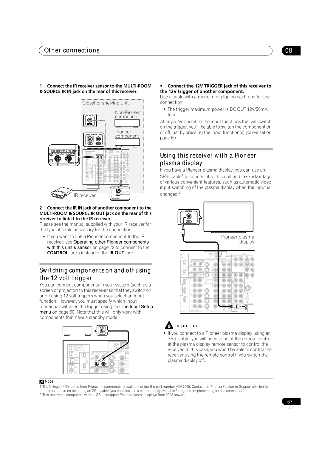
•Connect the 12V TRIGGER jack of this receiver to the 12V trigger of another component.
Use a cable with a mono
•The trigger maximum power is DC OUT 12V/50mA total.
After you’ve specified the input functions that will switch on the trigger, you’ll be able to switch the component on or off just by pressing the input function(s) you’ve set on page 60.
Using this receiver with a Pioneer plasma display
If you have a Pioneer plasma display, you can use an
SR+ cable1 to connect it to this unit and take advantage of various convenient features, such as automatic video input switching of the plasma display when the input is
changed.2
2Connect the IR IN jack of another component to the
Please see the manual supplied with your IR receiver for the type of cable necessary for the connection.
•If you want to link a Pioneer component to the IR receiver, see Operating other Pioneer components with this unit’s sensor on page 72 to connect to the CONTROL jacks instead of the IR OUT jack.
CONTROL
OUT
OOM
CE
L
Pioneer plasma display
ANTENNA | AUDIO | R | PRE OUT |
| PHONO | L |
Switching components on and off using the 12 volt trigger
You can connect components in your system (such as a screen or projector) to this receiver so that they switch on or off using 12 volt triggers when you select an input function. However, you must specify which input functions switch on the trigger using the The Input Setup menu on page 60. Note that this will only work with components that have a standby mode.
12V
TRIGGER
(ZONE3) |
|
|
| FM UNBAL 75Ω |
| AM LOOP |
|
|
|
|
|
| |
|
|
| MONITOR | IN |
|
|
|
| |||||
|
|
| IN | ROOM2(ZONE2) OUT | OUT |
| R ROOM2(ZONE2) L | CD |
|
| SUBW. | ||
| S400 |
| IR |
|
|
| OUT |
| IN |
|
|
|
|
|
|
|
| 12 V TRIGGER |
|
|
|
|
|
|
|
|
|
| (AUDIO) |
| 1 | 2 |
|
| DVD/ |
|
|
|
|
|
|
|
|
| IN1 |
| LD |
|
|
|
|
|
| ||
|
|
| (DC OUT 12VTOTAL 50mA MAX) |
| IN |
|
|
|
|
|
| ||
| S400 | ROOM2 |
|
|
|
| OUT |
|
|
|
| ||
|
|
| & SOURCE |
|
| TV |
|
|
|
|
|
| |
|
|
|
| MONITOR | IN2 |
| IN |
|
|
|
|
|
|
|
| (ZONE2) | OUT |
|
|
|
|
|
| R | L | ||
| HDMI | IN1 | OUT | IN1(DVD/LD) |
| SAT |
| TAPE |
|
| |||
| IN1 |
| Y | Y | IN2(TV) |
|
| IN |
|
|
|
| |
|
|
|
|
|
| IN |
|
|
| L |
| ||
|
|
|
|
|
|
|
| R |
|
|
| ||
|
|
|
|
| ASSIGNABLE |
| VIDEO1/ |
| FR |
| FL | iPod |
|
|
|
| PB | PB |
|
|
|
|
|
|
|
| |
|
|
|
|
| GAME1 |
|
|
|
|
| IN | ||
|
|
|
|
|
| IN |
| SUB W. | CENTER |
| |||
IN2 |
|
|
|
|
|
|
|
| |||||
NA- |
|
| PR | PR |
|
| OUT |
|
|
|
|
|
|
|
|
|
|
|
|
|
|
|
|
| |||
|
|
|
|
|
| DVR/ |
| SUR- |
|
|
|
| |
|
|
| IN2 | IN3 |
|
|
| ROUND |
|
|
| ||
|
|
|
|
| VCR 1 |
|
|
|
|
|
| ||
| OUT |
| Y | Y |
|
| IN |
|
|
|
|
|
|
|
|
|
|
|
|
|
|
|
|
|
|
| |
|
|
|
|
|
|
|
|
| R |
|
| L |
|
|
|
| PB | PB |
|
| OUT |
|
|
|
|
|
|
|
|
|
|
|
|
| DVR/ |
| R | SURROUND | L | ||
|
|
|
|
|
|
| VCR 2 |
|
|
| |||
|
|
|
|
|
|
|
|
|
|
| BACK |
|
|
|
|
| PR | PR |
|
| IN |
|
|
|
| CH |
|
|
|
|
|
| S | VIDEO | R | L |
| OUT | IN | IN |
|
|
|
| ASSIGNABLE | CONTROL |
|
|
| ||||||
DIGITAL |
| COMPONENT VIDEO | VIDEO |
| AUDIO |
|
|
|
| ||||
|
|
|
|
|
|
|
| ||||||
![]() Important
Important
|
|
|
|
| • If you connect to a Pioneer plasma display using an |
|
|
|
|
| SR+ cable, you will need to point the remote control |
|
|
|
| at the plasma display remote sensor to control the | |
&SOURCE |
|
|
|
| receiver. In this case, you won’t be able to control the |
/REC SEL |
|
|
|
| |
ROOM3(ZONE3) |
|
|
|
| |
OUT1 |
|
| FM UNBAL 75Ω | A |
|
| MONITOR | MULT | receiver using the remote control if you switch the | ||
OUT2 | IN | ROOM2(ZONE2) OUT | OUT |
| |
|
| ||||
S400 | IR |
|
| OUT | plasma display off. |
IN |
|
|
|
| |
USB |
|
|
|
|
|
AUDIO |
| 12 V |
|
|
|
(AUDIO) | 1 | 2 |
| DVD/ |
|
| IN1 | LD |
| ||
IN1 | (DC OUT 12VTOTAL 50mA MAX) | IN |
| ||
(SAT) | ROOM2 |
|
|
| |
S400 |
| & SOURCE |
| TV |
|
IN2 | (ZONE2) | MONITOR | IN2 | IN |
|
OUT |
|
|
| ||
(DVR/ |
| OUT |
|
|
|
![]() Note
Note
1The
2This receiver is compatible with all SR+ equipped Pioneer plasma displays from 2003 onward.
57
En