Other Settings
Chapter 10:
Other Settings
The Input Setup menu
You only need to make settings in the Input Setup menu if you didn’t hook up your digital equipment according to the default settings (see Input function default and possible settings on page 66). In this case, you need to tell the receiver what equipment is hooked up to which terminal so the buttons on the remote correspond to the components you’ve connected.
|
|
|
| PARAMETER |
| PARAMETER |
|
|
|
|
| EXIT | TUNE | TOOLS |
|
RECEIVER |
|
| SOURCE | TOP MENU |
| AUDIO DISPLAY | CH |
|
|
|
|
| MENU |
| |
|
|
|
|
|
| T.EDIT |
|
|
|
|
|
| ENTER | TV CTRL | RECEIVER |
DVD | BD | TV | HDMI | ST | ST |
| |
DVR 1 | DVR 2 | CD | PTY |
|
|
| |
SEARCH |
| RETURN |
| ||||
FM/AM |
|
| iPod USB | SETUP | TUNE | MAIN | ZONE 2 |
|
| iPod CTRL |
|
|
| ||
|
|
|
|
|
|
|
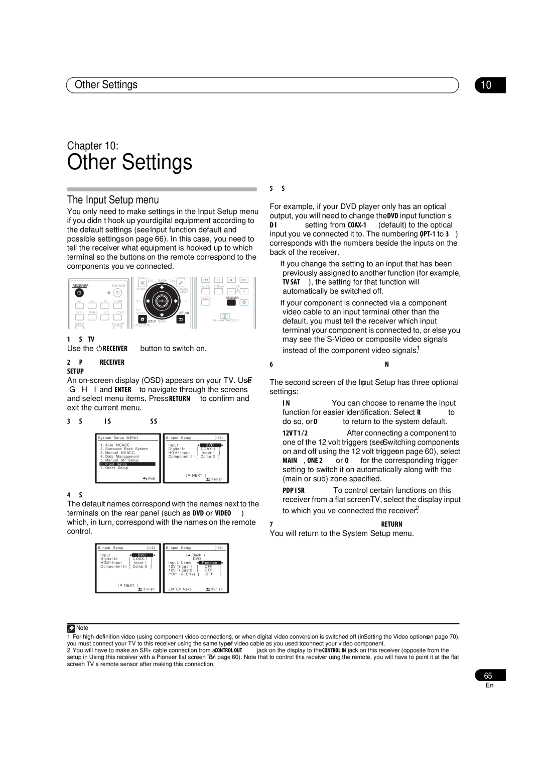
1Switch on the receiver and your TV. Use the RECEIVER button to switch on.
2Press RECEIVER on the remote control, then press
SETUP.
An
3Select ‘Input Setup’ from the System Setup menu.
System Setup MENU |
| 6.Input Setup | (1/2) | ||||||
1 | . Auto | MCACC |
| Input |
|
|
| ||
| DVD |
| |||||||
2 | . Surround Back System |
| Digital In | [ |
| ] | |||
3 | . Manual MCACC |
| HDMI Input | [ | ] | ||||
4 | . Data | Management |
| Component In [ | ] | ||||
5 | . Manual SP Setup |
|
|
|
|
| |||
| 6 | . Input | Setup |
|
|
|
|
|
|
| 7 | . Other | Setup |
|
|
|
|
|
|
|
|
| :Exit | ( | NEXT | ) |
| ||
|
|
|
|
|
| :Finish | |||
4Select the input function that you want to set up. The default names correspond with the names next to the terminals on the rear panel (such as DVD or VIDEO) which, in turn, correspond with the names on the remote control.
6.Input Setup | (1/2) |
| 6.Input | Setup |
|
|
| (1/2) | |||
Input |
|
|
|
|
| ( Back | ) |
|
| ||
| DVD |
|
|
|
|
| |||||
Digital In | [ | ] |
|
| DVD |
|
|
| |||
HDMI Input | [ | ] |
| Input | Name |
|
| Rename |
| ||
Component In [ | ] |
| 12V Trigger1 | [ |
| OFF |
| ] | |||
|
|
|
|
| 12V Trigger2 | [ | OFF | ] | |||
|
|
|
|
| PDP | In (SR+) | [ | OFF | ] | ||
( | NEXT | ) |
|
|
|
|
|
|
|
|
|
|
| :Finish |
| ENTER:Next |
|
| :Finish | ||||
10
5Select the input(s) to which you’ve connected your component.
For example, if your DVD player only has an optical output, you will need to change the DVD input function’s Digital In setting from
•If you change the setting to an input that has been previously assigned to another function (for example, TV SAT), the setting for that function will automatically be switched off.
•If your component is connected via a component video cable to an input terminal other than the default, you must tell the receiver which input terminal your component is connected to, or else you may see the
6When you’re finished, select ‘Next’ to continue to the next screen.
The second screen of the Input Setup has three optional settings:
•Input Name – You can choose to rename the input function for easier identification. Select Rename to do so, or Default to return to the system default.
•12V Trigger 1 / 2 – After connecting a component to one of the 12 volt triggers (see Switching components on and off using the 12 volt trigger on page 60), select MAIN, ZONE 2 or OFF for the corresponding trigger setting to switch it on automatically along with the (main or sub) zone specified.
•PDP In (SR+) – To control certain functions on this receiver from a flat screen TV, select the display input to which you’ve connected the receiver.2
7When you’re finished, press RETURN.
You will return to the System Setup menu.
![]() Note
Note
1For
2You will have to make an SR+ cable connection from a CONTROL OUT jack on the display to the CONTROL IN jack on this receiver (opposite from the setup in Using this receiver with a Pioneer flat screen TV on page 60). Note that to control this receiver using the remote, you will have to point it at the flat screen TV’s remote sensor after making this connection.
65
En