Rackmount Intelligent Pressure Scanners User’s Manual
Page
Pressure Systems, Inc 98RK-1 & 9816 User’s Manual
Table of Contents
Calibration 100
Start-up Software 144
Service 110
Troubleshooting Guide 136
150
Technical Support
Our Warranty
Our Company
Website and E-Mail Our Firmware Our Publication Disclaimer
This page left intentionally blank
Chapter General Information Introduction
Typical NetScanner System Configuration
Description of the Instruments
Options
Pressure Ranges
Manifolds and Pressure Connections
Communication Interfaces
98RK-1 Rear Panel
98RK-1 Scanner Interface Rack chassis
Chapter Installation and Set Up Unpacking and Inspection
Safety Considerations
98RK-1 Scanner Interface Rack User’s Manual on CD-ROM
Connections and Setup
1 98RK-1 Chassis Connections with 9816 Scanners
Connections for External Modules
Pressure Systems, Inc 98RK-1 & 9816 User’s Manual
Network Communications Hookup
Step
Initial Network Screen for Windows XP
Screen example is shown here
Pressure Systems, Inc 98RK-1 & 9816 User’s Manual
Pressure Systems, Inc 98RK-1 & 9816 User’s Manual
Pressure Systems, Inc 98RK-1 & 9816 User’s Manual
Wait 10 seconds before reconnecting
\ NUSS\NUSS.EXE
Pressure Systems, Inc 98RK-1 & 9816 User’s Manual
Nuss Initial Screen
Pressure Systems, Inc 98RK-1 & 9816 User’s Manual
Pressure Connections
98RK-1 Rear View
Expanded View of Model 9816 Intelligent
RUN Mode Inputs
Supply Air
CAL Mode Inputs
Pressure Systems, Inc 98RK-1 & 9816 User’s Manual
Purge Mode Inputs
Leak Mode Inputs
Cluster, Rack, and Slot Identification
Calibration Manifold Position Detector Circuit
98RK-1 Front Pull-out Tray Diagram Top and Front Views
Typical Depiction of C-R-S Scanner Identification
Acquiring Data
Chapter Programming and Operation Commands & Responses
Introduction
2 TCP/UDP/IP Protocols
Commands
General Command Format
Command Field
Position Field
Bit# Chan# Binary Hex
Responses
Format Field
An Acknowledge with Data response, or
Interpreting Offset Values Re-zero Calibration Adjustment
Interpreting Gain Values Span Calibration Adjustment
Functional Command Overview
Interpreting Engineering Units Output
Module Data Acquisition
Pressure Systems, Inc 98RK-1 & 9816 User’s Manual
Delivery of Acquired Data to Host
Network Query and Control Functions
Other Functions
Detailed Command Description Reference
Power-up Clear
Psi9000 Query Network
Response
Power UP Clear Command a
Command
Example
Reset Command B
CONFIGURE/CONTROL MULTI-POINT Calibration Command C
Command C ii dddd
Command C 00 pppp npts ord avg
Response a
00 F 3 1 64 Read response
Pnt pppp.pppp
Response Pppp.pppp pppp.pppp
01 1 -2.5 C 01 2 0.0 C 01 3
‘ 02’ is the sub-command index ii for Calculate & Apply
02 w08 w09
‘ 03’ is the sub-command index ii for Abort
Dddd dddd
Read Transducer Voltages Command
Vpppppf
Converts each internal response datum value from Max.char
V11110
V300000
005880
Calculate and SET Gains Command Z
Zpppp
Gggg g.gggg
Z00F8 14.8890 Response 01289 1.06953 1.03750 0.99704
Read Transducer A/D Counts Command a
Apppppf
A300000
A11110
32767.000000 -32700.000000 10.000000
10.000000
Read HIGH-SPEED Data Command b
Aaaabbbbcccc..rrrr
Aaaabbbbcccc .. rrrrpppp
Autonomous
DEFINE/CONTROL Autonomous Host Streams Command c
Command Ii dddd
Packet
Pressure Systems, Inc 98RK-1 & 9816 User’s Manual
St ppppp sync per f num
Pressure Systems, Inc 98RK-1 & 9816 User’s Manual
00 1 000F 0 1 7 0 c 00 2 00F0 0 2 7 0 c 00 3 FF00 0 4 7
Command c- Sub-command Index 01 Start Stream
Command 01 st
Example
Command c- Sub-command Index 02 Stop Stream
Command 02 st
Command c- Sub-command Index 03 Clear Stream
Command 03 st
02 0 c 03 3 c 01
Command c Sub-command Index 04 Return Stream Information
Command 04 st
Ffff 0 20 7
Selecting too many other data groups will compromise
Command c Sub-command Index 05 Select Data in a Stream
St bbbb
Module performance
Bit # Chan # Binary Hex
05 1 0013 Read response
St pro remport ipaddr
06 0 1 7500 Read response
06 0
Calculate and SET Offsets Command h
Hpppp
HF000 Response 0010 0.0020 0.0015
Read Temperature Counts Command m
Mpppppf
Converts each internal response datum value from Max.ch
M11110
Read Temperature Voltages Command n
Command n p ppppf
N11110
53013 0.541698 0.503633
Returned value Set Digit hex or other decimal
Read Module Status Command q
Hhhh
Firmware Version, as hex value
IP Address Resolution Method, as hex state
Auto UDP Broadcast@Reset, as hex state
+NOTE
9816
Read HIGH-PRECISION Data Command r
Command r p ppppf
R11110
234000 0.989500 1.005390
Description
Read Transducer Temperature Command t
Command tpppppf
T11110
Read Internal Coefficients Command u
Ufaacc-cc
Converts each internal value from Max.char
Span Cal Adjustment gain term
Date of Factory Calibration see end-of-table note
EU Pressure Conversion Scaler default =
Transducer Coefficient Description Datum Type
Other Coefficients Description Datum Type
Example
Download Internal Coefficients Command
Vfaacc-ccdddd dddd
Converts each datum parameter value ‘ dddd’ from Max.char
V00800-01 0.000 1.000 Response returned is
V01101 6.894757 Response returned is
SET/DO Operating OPTIONS/FUNCTIONS Command w
Wii dd eeee
Energize C3 Set Cal Valves to Purge or Leak Chart
Energize C1 Set Cal Valves to CAL/RE-ZERO or Chart
Set Number of A/D Samples to Average . default =
Set Maximum Temperature Alarm Set Point in 0 C
Enable Source Air Check default Disable Source Air Check
Set Minimum Source Air Pressure per eeee as decimal
W1200
W0C01
Network Query UDP/IP Command psi9000
Subnet, iparpst, udpast, pwrst, rack, cluster, slot
See response above
RE-BOOT Module UDP/IP Command psireboot
Command Psireboot ethadr
Psireboot 12-34-56-78-90-12 Response None
Command Psirarp ethadr
Psirarp 12-34-56-78-90-12 Response None
Chapter Calibration Introduction
Figures 4.1 Pneumatic Diagrams of the Calibration Manifold
Re-zero Calibration
Re-zero Calibration Valve Control
Span Calibration
Re-zero Calibration Summary
Description TCP/IP Data
Span Calibration Valve Control
Span Calibration Summary
See Sec
Integrated Multi-Point Calibration Adjustment
See Section
Calibration Valve Control
Coefficients in transducer non-volatile memory
Multi-Point Calibration Summary
Line Pressure Precautions
Coefficient Storage
Chapter Service Maintenance
Exploded View of 9816 Calibration Manifold
With Upgraded Purge Block
Component Section
Component Cross Reference
Common Maintenance
Module Disassembly
PC299 Board
Electronic Circuit Board Replacement
3.1 PC-206 Amplifier/Multiplexer Board
Calibration Valve Out of its Case Showing PC-206 Board
3.2 PC-299 Ethernet Microprocessor/A-D Board
PC-299 Board PC-299 Board with Cable Connections
Valve Manifold Position Detector Circuit
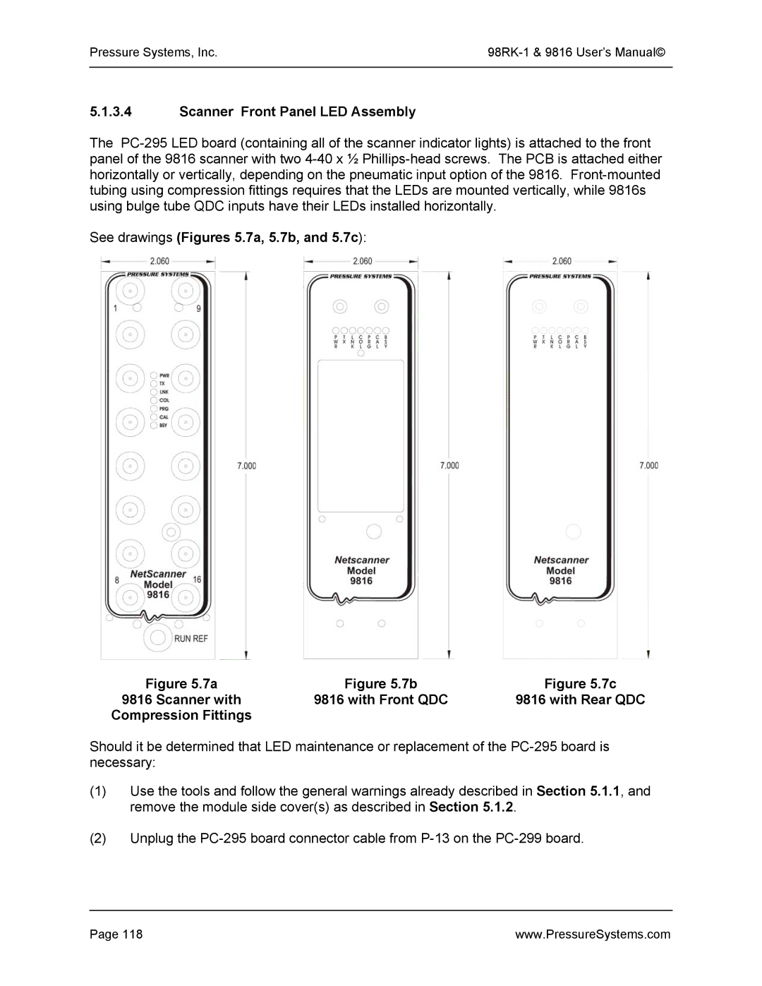
Scanner Front Panel LED Assembly
See drawings Figures 5.7a, 5.7b, and 5.7c Scanner with
Compression Fittings
Pressure Systems, Inc 98RK-1 & 9816 User’s Manual
Hex-head standoff screws used on DH200 positions 2
Replacement of Transducers
Top View of DH200
Be over tightened or else the screw may break
Model 9816 Solenoid Replacement
.9a
Schematic of 9816 Solenoids
Solenoids Attached to Module
Replacement of O-Rings
6.1 DH200 Pressure Transducer O-Ring Replacement
DH200 Transducer O-Ring Replacement
Tubing Plate O-Ring Replacement
Adapter Plate O-Ring Replacement
Calibration Manifold Piston O-Ring Replacement
Solenoid Valve O-Ring Replacement
For non-glued flared post O-ring replacement
Module Rear Manifold O-Ring Replacement
For glued O-ring replacement
For all
Solenoid Valve O-Ring Replacement
Pressure Systems, Inc 98RK-1 & 9816 User’s Manual
Supply Air and Purge Air Sensing Transducers
As you are looking at the pneumatic backplane, the two
Pressure rating of the supply-sensing transducer is 150 psi
Front Pull-out Slide Tray
Upgrading Module Firmware
Upgrading Firmware via Host TCP/IP Port
Update Firmware Screen
Checking 98RK-1 Scanner Interface Rack Power-up Sequence
Checking Module LED Power-Up Sequence
Checking Module TCP/IP Communications
Module IP Address Assignment
Host IP Address Assignment for Windows Operating Systems
Pressure Systems, Inc.98RK-1 & 9816 User’s Manual
Verifying Host TCP/IP Communications
Zero and Gain Calibration Troubleshooting
Pressure Systems, Inc 98RK-1 & 9816 User’s Manual
Chapter Start-up Software Introduction
Appendix a Cable Design
NetScanner Ethernet Interface Cable
Appendix B NetScanner System Range Codes
Range Code Full Scale Pressure Minimum Calibration
Pressure Systems, Inc.98RK-1 & 9816 User’s Manual
Appendix C Creating a Shortcut Icon
Pressure Systems, Inc 98RK-1 & 9816 User’s Manual
Appendix D Merchandise Return Procedure
Bill To and Ship To address
Headquarters/Factory European Office