Pressure Systems, Inc. | |
|
|
2.3.4.6Calibration Manifold Position Detector Circuit
The transducer calibration manifold position detector circuit uses reflective infrared sensors to sense the actual position of the manifold valve block. The block, located within the valve assembly, is shifted to a desired position by pneumatic pistons positioned around the block.
Two reflective infrared sensors, which sense the position of the block by the reflection of the sensor infrared beam from the block surface, are mounted into the assembly. If the block is in front of the sensor, a low level logic signal is output by the sensor, indicating the presence of the block. If the block is not in front of the sensor, the infrared beam is not reflected and the sensor outputs a logic high signal.
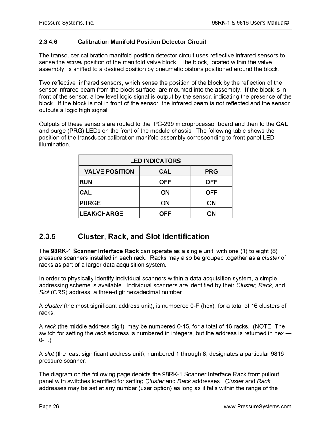
Outputs of these sensors are routed to the
LED INDICATORS
VALVE POSITION | CAL | PRG |
RUN | OFF | OFF |
CAL | ON | OFF |
PURGE | ON | ON |
LEAK/CHARGE | OFF | ON |
2.3.5Cluster, Rack, and Slot Identification
The
In order to physically identify individual scanners within a data acquisition system, a simple addressing scheme is available. Individual scanners are identified by their Cluster, Rack, and Slot (CRS) address, a
A cluster (the most significant address unit), is numbered
A rack (the middle address digit), may be numbered
A slot (the least significant address unit), numbered 1 through 8, designates a particular 9816 pressure scanner.
The diagram on the following page depicts the
Page 26 | www.PressureSystems.com |
