DTV-947
Page
Table of Contents
Table of Contents
10-4
10-1
Overview 10-1
10-3
11-1
10-15
OWNER’S Record
Safety Instructions
Installation Instructions
On Safety
On servicing
Mains lead Power cord with CEE 7 plug
Power cord with Ansi 73.11 plug
On installation
IR Sensor
Location and Function of Controls
RS 232 Input Port
RS 232 Output Port
For Future Use
IR Transmission Indicator
Help Not used
Sound controls Not used
Connections
AC Power mains Cord Connection
Power Check
Switching On/Off
Video input selection
Connecting a Composite Video Source to the BNC video input
Input selection
Connecting an S-Video or Video source to the S-Video input
RGB3S or RG3sB input selection
Connecting a RGB Analog source
Connecting a RGB Analog source with Tri-level sync
Rgbs or RGsB input selection
Connecting a Component source
Connecting a Component source with Tri-level sync
YYB-YS or R-YYsB-Y input selection
RS232 OUT Comm Port Remote
YYB-Y3S or R-YY3sB-Y input selection
Controlling
Controlling
Pause key
Analog Picture Controls
Adjustment mode
Start UP of the Adjustment Mode
Compose
Random Access Adjustment Mode
Starting up the random access adjustment mode
Overview ‘Random Access Adjustment’ mode
Internal Cross Hatch Pattern
Selecting Setup Pattern
Color Balance
Random access adjustment mode selection menu
Picture Tuning
Sync Fast/Slow Adjustment
Peaking
Color Select
Color Select
Geometry
Geometry Adjustments
Horizontal Phase Adjustment
Phase Raster Shift
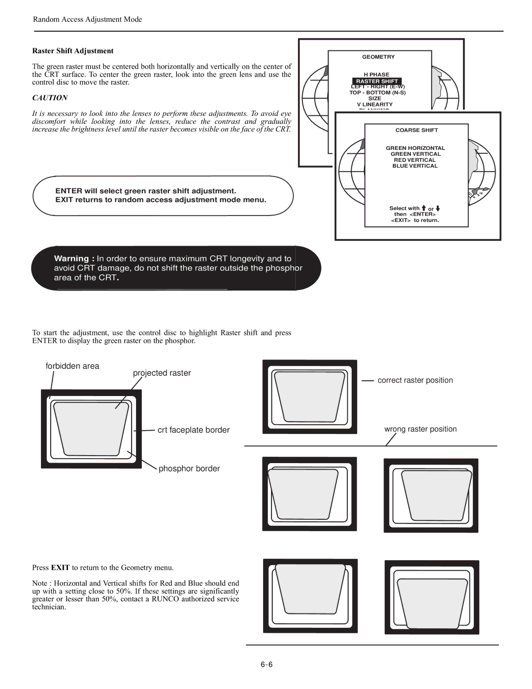
Raster Shift Adjustment
Left Right E-W
Left-Right east-west Adjustments
TOP Bottom N-S
Top-Bottom north-south Adjustments
Size Adjustment
Vertical Linearity Adjustment
Linearity
Left blanking Top blanking Right blanking Bottom blanking
Blanking Adjustments
Convergence Adjustment
Coarse Convergence Adjustments
Convergence
Vertical corners
Fine Convergence Adjustments
Service Mode
Starting up the Service mode
Overview flowchart ‘Service’ mode
Projector SET-UP
Runco
Projector Set-up
Identification
Change password
Total Run Time
Change Language
Change Projector Address
Power up mode
Change Projector Address
Change baudrate
Copy a Block
Memory management
Copy a block
Memory Management
Delete a Block
Deletion of blocks
Deleting block by block
Deletion of all blocks
All settings to midposition
Undo all settings to midpos
Convergence mid
Undo green convergence mid
Common Settings
Undo R & B convergence mid
Green convergence mid
G2 Adjustment
CRT run in cycle
CRT RUN in Cycle Projector Warm UP
Enter to select the projector warm up menu
Nal # pattern and restart the CRT run in option
Exit returns to the Path Selection main menu
Projector warm up
12C Diagnostics
I2C Diagnostics
MESSAGES, WARNINGS, and Failures
Messages, Warnings, and Failures
RS-232 Control
Hardware Configuration
Sending a Record single instruction
Decimal values
Command Code List
$02,$00,$00,$51,$0A,$00,$00,$00,$01,$5C
Sharpness
Overview
Quick Guide to using the EYE-QTMsystem
Compact, built-in system
EYE-QTMAUTOCONVERGENCE
Easy-to-use, high precision automatic convergence system
Easy-to-use, high precision automatic geometry system
Access to EYE-QTMON-SCREEN Menus
EYE-QTMMENU
EYE-QTMAutoconvergence
Setting the Configuration
EYE-QTMSETUP
Focusing the Camera Lens
Centering the Camera Horizontally
Centering the Camera
Centering the Camera Vertically
TOUCH-UP on Source ON/OFF
Appendix
TOUCH-UP on Timer
Adjusting Other Sources
Reference Source
Learn Reference
Learning a Reference
On Current Source
Adjusting Screen Size
TOUCH-UP
Align on Current Source
Align from Midposition on Current Source
On ALL Sources
TOUCH-UP on ALL Sources
Align on ALL Sources
Error Messages
Align from Midposition on ALL Sources
Interrupting the Automatic Convergence Process
No Pattern Error
Status Reporting Forced Break
Status Forced break
EYE-Q
10-16
Specifications
VHD Controller Manual
Table of Contents
Avertissement
Remarque
Safety Tips
General Description
Features and Benefits
Front Panel
Rear Panel
Front and Rear Panel Descriptions
RGB Output
Power Input
Program Button
Remote Control Description
Direct Access Buttons
LED
Component Input
Connection Examples
Composite Video Input
Video Input
Quick SET-UP Guide
Getting Started
Overall Functional Description
Main Menu
Menu Description and Navigation
Menu Description and Navigation
Picture Quality Adjustments
Contrast
Tint
Color
Brightness
Menu Description and Navigation Sharpness
Luma Enhance
Chroma Enhance
First, the Basics
Aspect Ratios
Aspect Ratios
Active image area Actual screen area Blanked cut off Areas
Side
Top
Ascii
RS-232 Protocol
Supplied Accessories
Specifications
Page
RUMA-003500 rev Tripaldi Way Hayward, CA