1 - SAGEM F@st™ 1000 modem overview
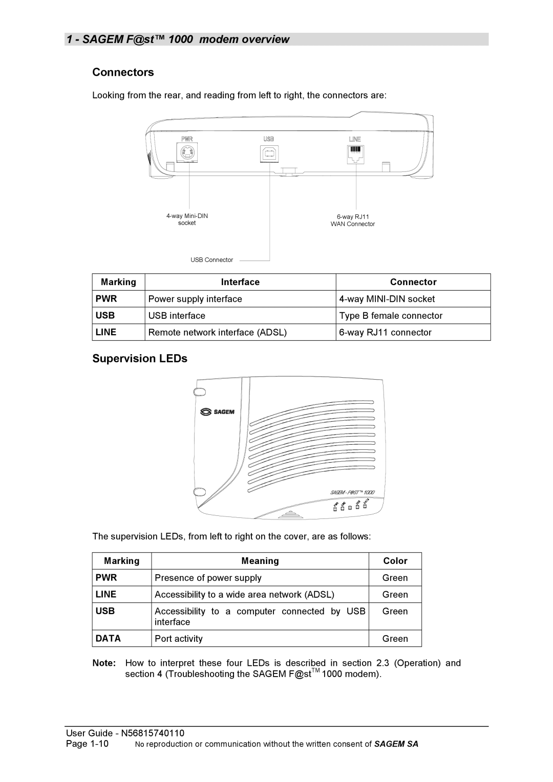
Connectors
Looking from the rear, and reading from left to right, the connectors are:
1 2 3 4 5 6
|
| ||
| socket | WAN Connector | |
| USB Connector |
|
|
|
|
|
|
Marking | Interface |
| Connector |
|
|
|
|
PWR | Power supply interface |
| |
|
|
|
|
USB | USB interface |
| Type B female connector |
|
|
|
|
LINE | Remote network interface (ADSL) |
| |
|
|
|
|
Supervision LEDs
The supervision LEDs, from left to right on the cover, are as follows:
Marking | Meaning | Color |
|
|
|
PWR | Presence of power supply | Green |
|
|
|
LINE | Accessibility to a wide area network (ADSL) | Green |
|
|
|
USB | Accessibility to a computer connected by USB | Green |
| interface |
|
DATA | Port activity | Green |
|
|
|
Note: How to interpret these four LEDs is described in section 2.3 (Operation) and section 4 (Troubleshooting the SAGEM F@stTM 1000 modem).
User Guide - N56815740110
Page