4 - Troubleshooting the SAGEM F@stTM 1000 modem
4.2Interpreting the LEDs
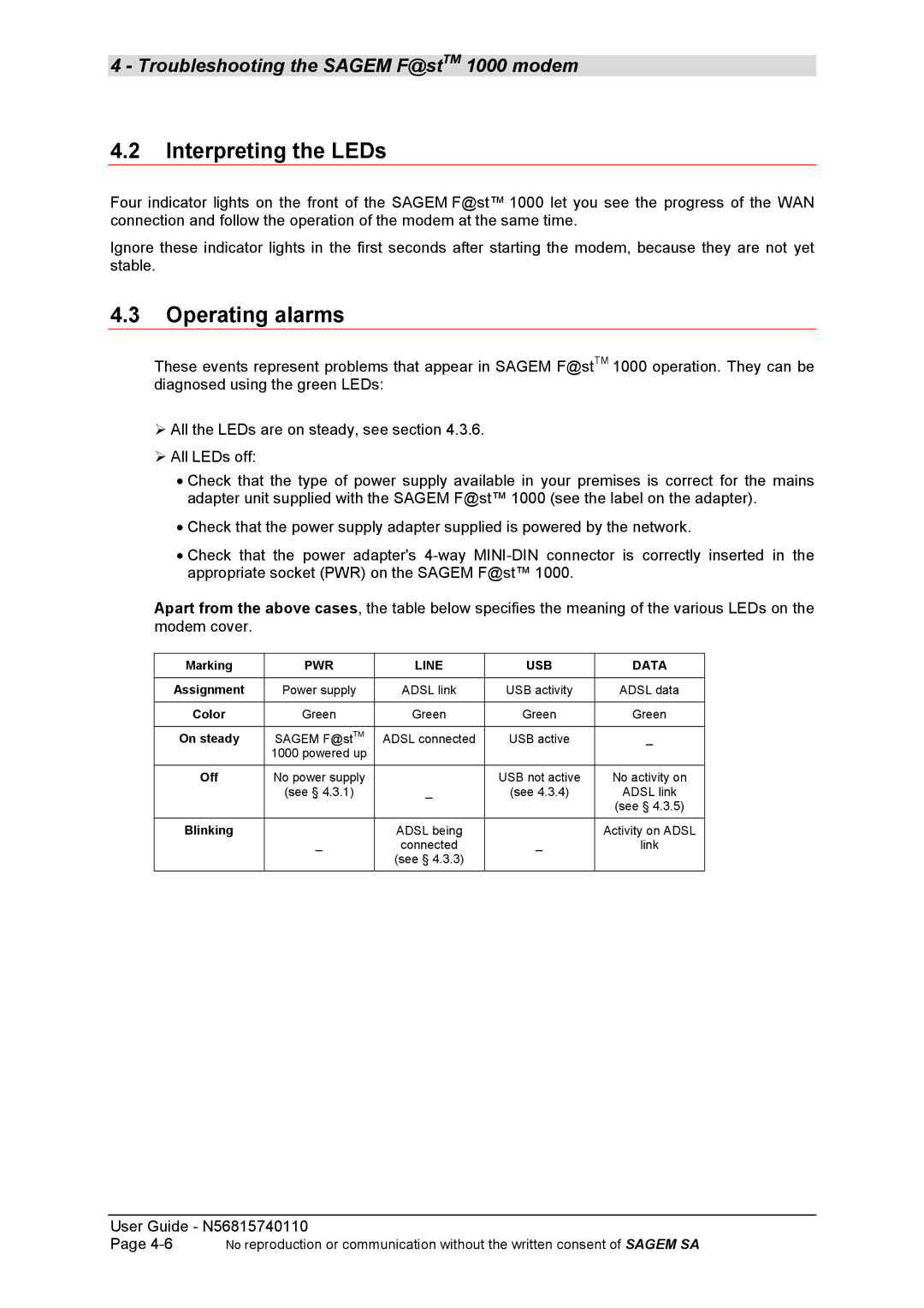
Four indicator lights on the front of the SAGEM F@st™ 1000 let you see the progress of the WAN connection and follow the operation of the modem at the same time.
Ignore these indicator lights in the first seconds after starting the modem, because they are not yet stable.
4.3Operating alarms
These events represent problems that appear in SAGEM F@stTM 1000 operation. They can be diagnosed using the green LEDs:
!All the LEDs are on steady, see section 4.3.6.
!All LEDs off:
•Check that the type of power supply available in your premises is correct for the mains adapter unit supplied with the SAGEM F@st™ 1000 (see the label on the adapter).
•Check that the power supply adapter supplied is powered by the network.
•Check that the power adapter's
Apart from the above cases, the table below specifies the meaning of the various LEDs on the modem cover.
Marking | PWR | LINE | USB | DATA |
|
|
|
|
|
Assignment | Power supply | ADSL link | USB activity | ADSL data |
|
|
|
|
|
Color | Green | Green | Green | Green |
|
|
|
|
|
On steady | SAGEM F@stTM | ADSL connected | USB active | _ |
| 1000 powered up |
|
|
|
|
|
|
|
|
Off | No power supply |
| USB not active | No activity on |
| (see § 4.3.1) | _ | (see 4.3.4) | ADSL link |
|
|
|
| (see § 4.3.5) |
|
|
|
|
|
Blinking | _ | ADSL being | _ | Activity on ADSL |
| connected | link | ||
|
| (see § 4.3.3) |
|
|
|
|
|
|
|
User Guide - N56815740110
Page | No reproduction or communication without the written consent of SAGEM SA |
