8-4. Auto Address Setting
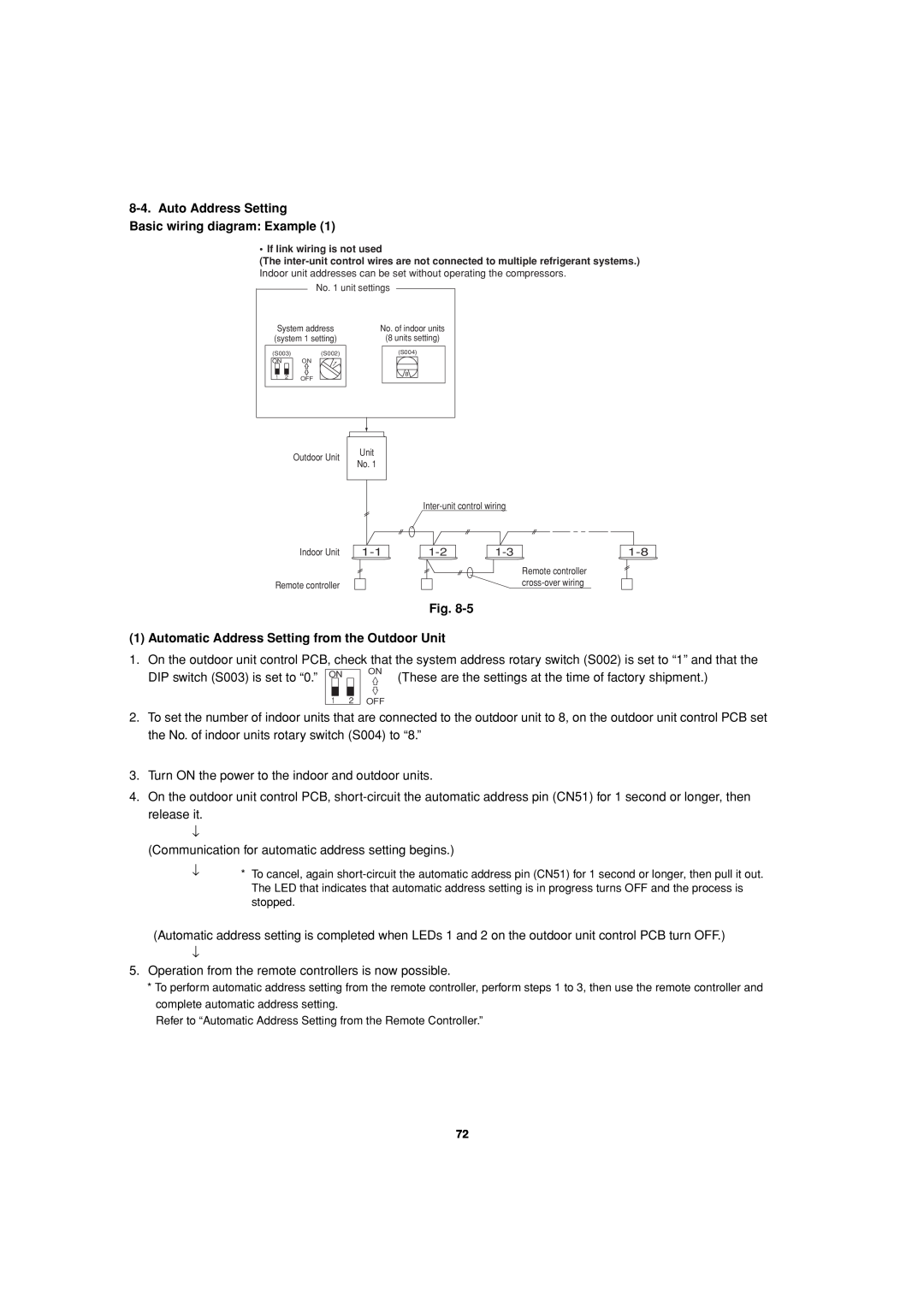
Basic wiring diagram: Example (1)
• If link wiring is not used
(The
No. 1 unit settings
System address (system 1 setting)
(S003) (S002)
ON ON
1 2 OFF
No. of indoor units
(8 units setting)
(S004)
8
Outdoor Unit | Unit | |
No. 1 | ||
|
Indoor Unit | ||||
|
|
|
| Remote controller |
Remote controller |
|
|
|
Fig.
(1) Automatic Address Setting from the Outdoor Unit
1. On the outdoor unit control PCB, check that the system address rotary switch (S002) is set to “1” and that the
DIP switch (S003) is set to “0.” ON | ON | (These are the settings at the time of factory shipment.) |
|
1 2 OFF
2.To set the number of indoor units that are connected to the outdoor unit to 8, on the outdoor unit control PCB set the No. of indoor units rotary switch (S004) to “8.”
3.Turn ON the power to the indoor and outdoor units.
4.On the outdoor unit control PCB,
(Communication for automatic address setting begins.)
↓* To cancel, again
(Automatic address setting is completed when LEDs 1 and 2 on the outdoor unit control PCB turn OFF.)
↓
5.Operation from the remote controllers is now possible.
*To perform automatic address setting from the remote controller, perform steps 1 to 3, then use the remote controller and complete automatic address setting.
Refer to “Automatic Address Setting from the Remote Controller.”
72