Interface to the User Program in the
2.3Meaning of the Data in the Digital Module
Overview
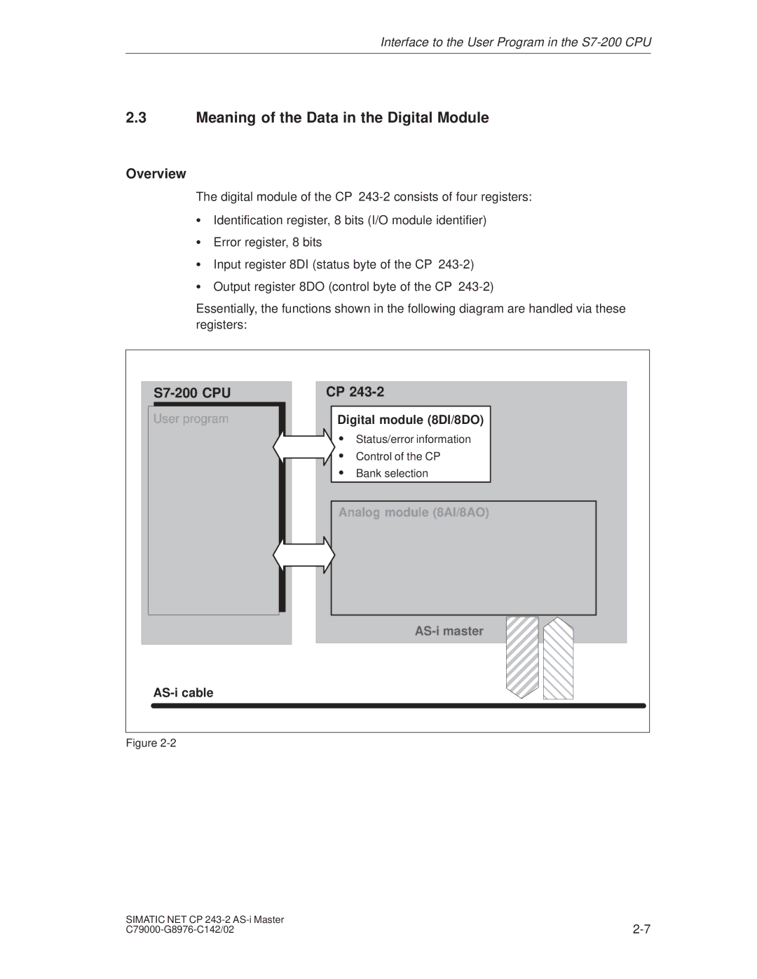
The digital module of the CP
SIdentification register, 8 bits (I/O module identifier)
SError register, 8 bits
SInput register 8DI (status byte of the CP
SOutput register 8DO (control byte of the CP
Essentially, the functions shown in the following diagram are handled via these registers:
| CP |
| |
User program | Digital module (8DI/8DO) |
| |
| S | Status/error information |
|
| S Control of the CP |
| |
| S | Bank selection |
|
| Analog module (8AI/8AO) |
| |
|
| ÍÎÎ | |
|
| ||
Figure |
|
| |
SIMATIC NET CP | |
