Interface to the User Program in the
2.3.4Control Byte (Output Register 8DO)
Meaning for the User Program
The user program controls the data exchange with the CP
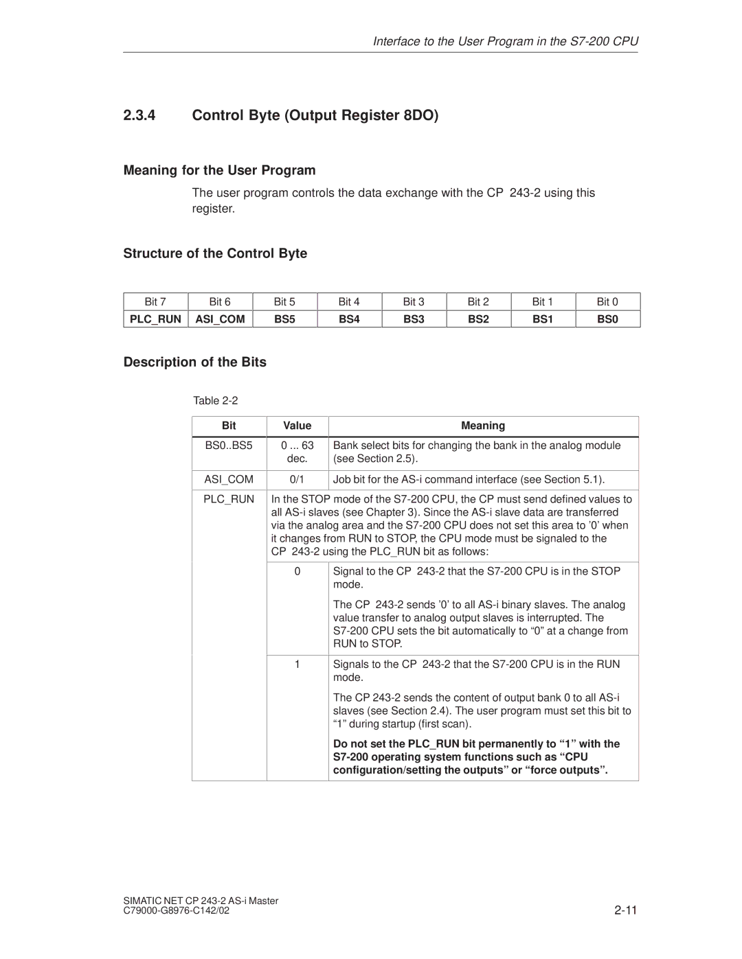
Structure of the Control Byte
Bit 7 | Bit 6 |
|
|
PLC_RUN ASI_COM
Bit 5
BS5
Bit 4
BS4
Bit 3
BS3
Bit 2
BS2
Bit 1
BS1
Bit 0
BS0
Description of the Bits
Table
Bit
BS0..BS5
ASI_COM
PLC_RUN
Value | Meaning |
|
|
0 ... 63 | Bank select bits for changing the bank in the analog module |
dec. | (see Section 2.5). |
|
|
0/1 | Job bit for the |
|
|
In the STOP mode of the
0Signal to the CP
The CP
1Signals to the CP
The CP
Do not set the PLC_RUN bit permanently to ª1º with the
SIMATIC NET CP | |