Interface to the User Program in the S7-200 CPU
2.5.1Analog Input Area
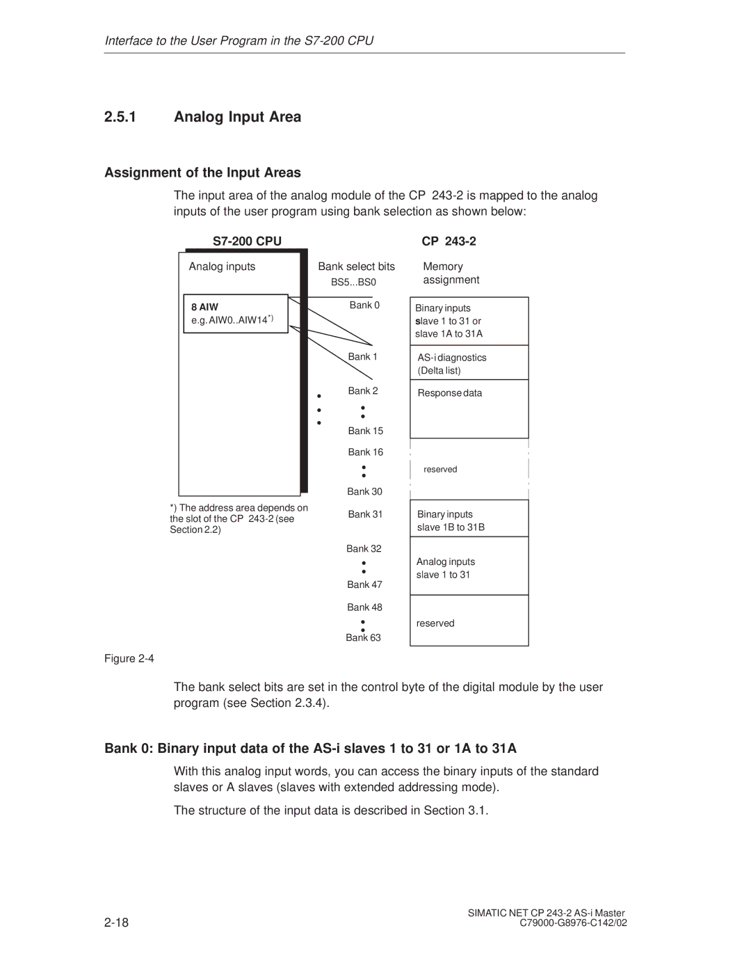
Assignment of the Input Areas
The input area of the analog module of the CP
S7-200 CPU
CP
Analog inputs
8 AIW
e.g. AIW0..AIW14*)
*) The address area depends on the slot of the CP
Bank select bits
BS5...BS0
Bank 0
⋅ | Bank 1 |
⋅ | |
⋅ |
|
⋅ | Bank 2 |
| Bank 15 |
| ⋅ |
| Bank 16 |
| Bank 30 |
| Bank 31 |
| ⋅ |
| Bank 32 |
| Bank 47 |
| ⋅ |
| Bank 48 |
| Bank 63 |
Memory assignment
Binary inputs
slave 1 to 31 or slave 1A to 31A
Response data
reserved
Binary inputs slave 1B to 31B
Analog inputs slave 1 to 31
reserved
Figure
The bank select bits are set in the control byte of the digital module by the user program (see Section 2.3.4).
Bank 0: Binary input data of the
With this analog input words, you can access the binary inputs of the standard slaves or A slaves (slaves with extended addressing mode).
The structure of the input data is described in Section 3.1.
SIMATIC NET CP | |