Command Interface
General Structure of the Command Buffer
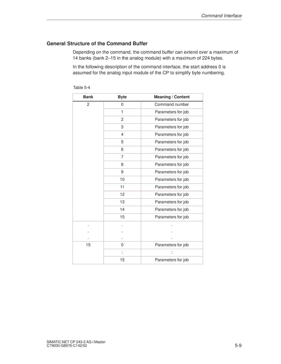
Depending on the command, the command buffer can extend over a maximum of 14 banks (bank 2±15 in the analog module) with a maximum of 224 bytes.
In the following description of the command interface, the start address 0 is assumed for the analog input module of the CP to simplify byte numbering.
Table
Bank
2
.
.
.
15
Byte
0
1
2
3
4
5
6
7
8
9
10
11
12
13
14
15
.
.
.
0
:
15
Meaning / Content
Command number
Parameters for job
Parameters for job
Parameters for job
Parameters for job
Parameters for job
Parameters for job
Parameters for job
Parameters for job
Parameters for job
Parameters for job
Parameters for job
Parameters for job
Parameters for job
Parameters for job
Parameters for job
.
.
.
Parameters for job
:
Parameters for job
SIMATIC NET CP | |