Release 11/02 | Unpacking and Installing the Panel PC 670/870 |
L5 ±0.2
*) |
112 ±0.5
Drill hole for screw fixings
M6/∅7
A1 ±1
*) |
L3 ±1 | L3 ±1 | 112 ±0.5 |
S1 ±1 | S2 ±1 |
|
|
| Pressure points |
|
| for clamps |
L2 +1 | L1 +1 | 112 ±0.5 56 ±1 |
|
| |
S1 ±1 | S1 ±1 |
|
A2 ±1
Clamp with grub screws
Rz 120 (in gasket area)
Gasket area
L4 ±0.2
min. 1.5 – max. 6
Operating units | L1 | L2 | L3 | L4 | L5 | A1 | A2 | S1 | S2 |
(a) with |
|
|
|
|
|
|
|
|
|
450 | 290 | 78 | 465 | 235 | 16 | 10 | – | – | |
450 | 321 | 51 | 465 | 279 | 16 | 17 | – | – | |
(b) with touchscreen front panels: |
|
|
|
|
|
|
|
|
|
368 | 290 | – | – | – | 16 | 10 | 35 | 19 *) | |
450 | 290 | 81 | 465 | 235 | 16 | 10 |
| (8HE) | |
– | – |
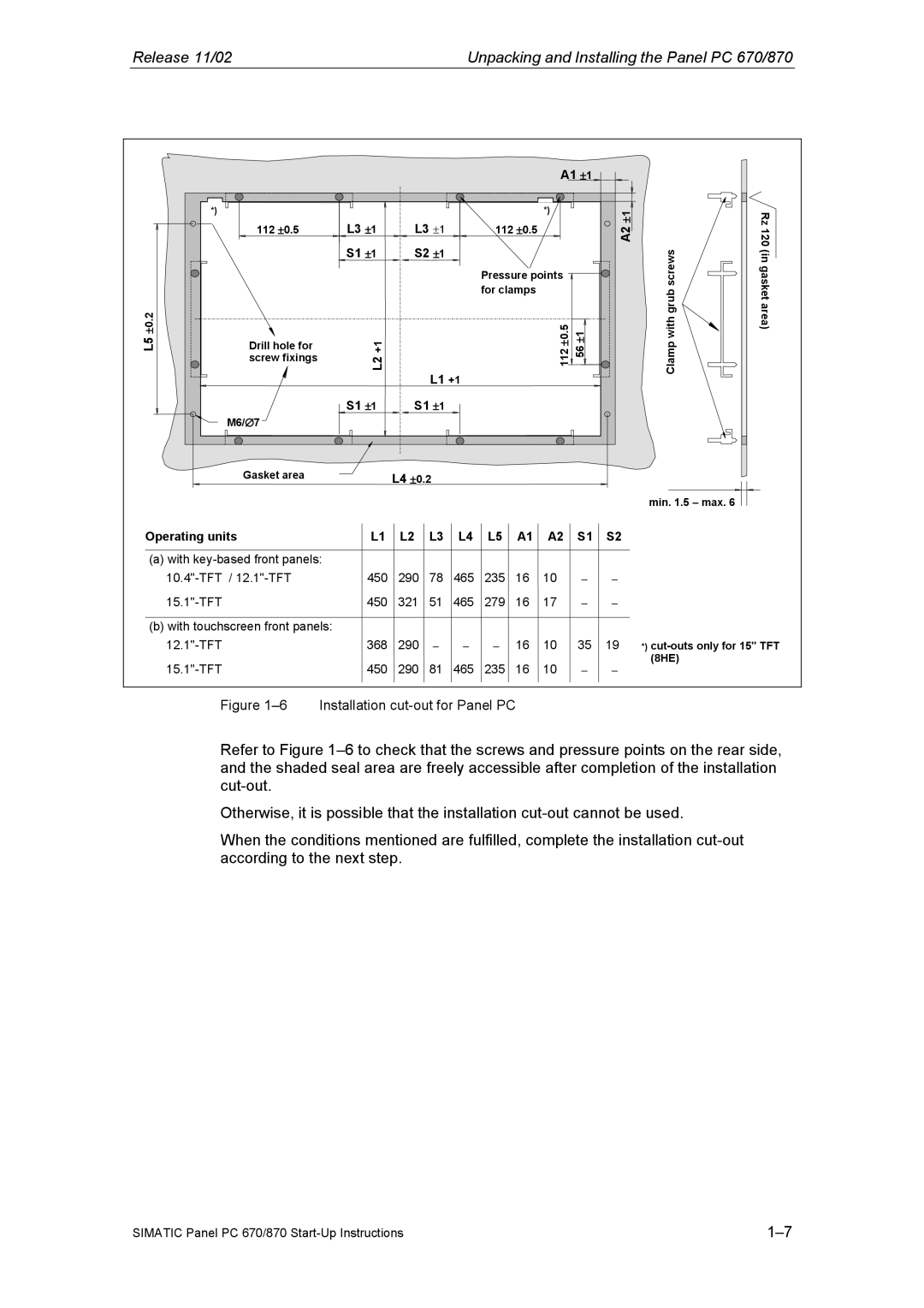
Figure 1–6 Installation cut-out for Panel PC
Refer to Figure
Otherwise, it is possible that the installation
When the conditions mentioned are fulfilled, complete the installation
SIMATIC Panel PC 670/870 |