Unpacking and Installing the Panel PC 670/870 | Release 11/02 |
Additional permissible installation position for the computer unit complying with UL508/CSA 22.2 No. 142
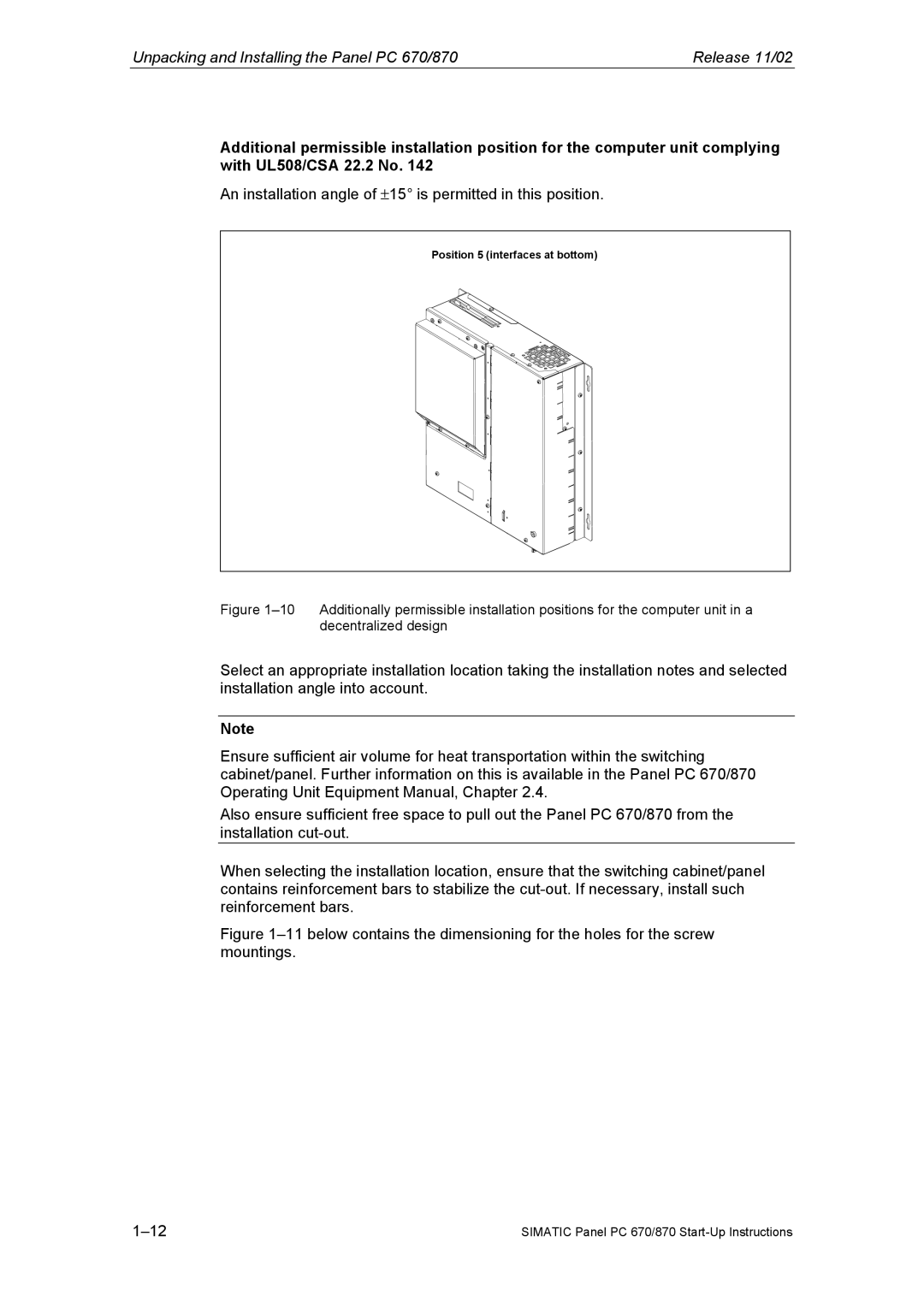
An installation angle of ±15° is permitted in this position.
Position 5 (interfaces at bottom)
Figure 1–10 Additionally permissible installation positions for the computer unit in a decentralized design
Select an appropriate installation location taking the installation notes and selected installation angle into account.
Note
Ensure sufficient air volume for heat transportation within the switching cabinet/panel. Further information on this is available in the Panel PC 670/870 Operating Unit Equipment Manual, Chapter 2.4.
Also ensure sufficient free space to pull out the Panel PC 670/870 from the installation
When selecting the installation location, ensure that the switching cabinet/panel contains reinforcement bars to stabilize the
Figure 1–11 below contains the dimensioning for the holes for the screw mountings.
SIMATIC Panel PC 670/870 |