Unpacking and Installing the Panel PC 670/870 | Release 11/02 |
Making the installation | Step 7 |
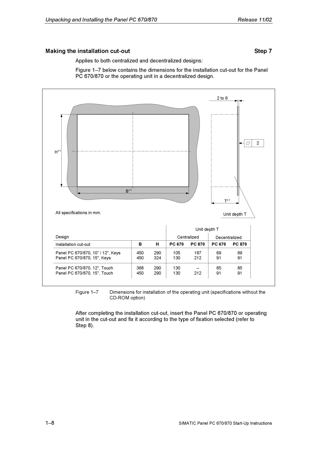
Applies to both centralized and decentralized designs:
Figure 1–7 below contains the dimensions for the installation cut-out for the Panel PC 670/870 or the operating unit in a decentralized design.
|
|
|
|
| 2 to 6 |
|
|
|
|
|
|
| 2 |
H+1 |
|
|
|
|
|
|
| B+1 |
|
|
|
|
|
|
|
|
|
| T+1 |
|
All specifications in mm. |
|
|
|
| Unit depth T | |
|
|
|
|
| ||
|
|
|
| Unit depth T |
| |
Design |
|
| Centralized | Decentralized | ||
Installation | B | H | PC 670 | PC 870 | PC 670 | PC 870 |
Panel PC 670/870, 10” / 12", Keys | 450 | 290 | 105 | 187 | 69 | 69 |
Panel PC 670/870, 15", Keys | 450 | 324 | 130 | 212 | 91 | 91 |
Panel PC 670/870, 12", Touch | 368 | 290 | 130 | – | 85 | 85 |
Panel PC 670/870, 15", Touch | 450 | 290 | 130 | 212 | 91 | 91 |
Figure 1–7 Dimensions for installation of the operating unit (specifications without the CD-ROM option)
After completing the installation
SIMATIC Panel PC 670/870 |