5 Handling
5.1Mounting and installation
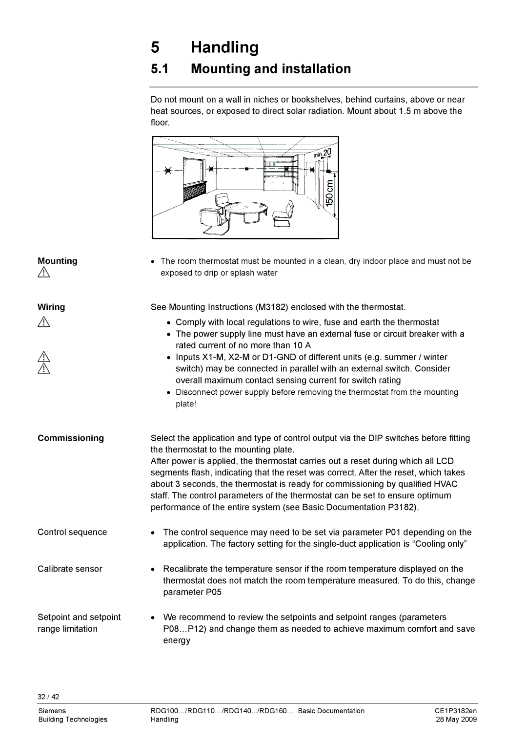
Do not mount on a wall in niches or bookshelves, behind curtains, above or near heat sources, or exposed to direct solar radiation. Mount about 1.5 m above the floor.
Mounting | • The room thermostat must be mounted in a clean, dry indoor place and must not be | |
| exposed to drip or splash water | |
Wiring | See Mounting Instructions (M3182) enclosed with the thermostat. | |
| • | Comply with local regulations to wire, fuse and earth the thermostat |
| • | The power supply line must have an external fuse or circuit breaker with a |
| • | rated current of no more than 10 A |
| Inputs | |
|
| switch) may be connected in parallel with an external switch. Consider |
|
| overall maximum contact sensing current for switch rating |
| • | Disconnect power supply before removing the thermostat from the mounting |
|
| plate! |
Commissioning | Select the application and type of control output via the DIP switches before fitting | |
| the thermostat to the mounting plate. | |
| After power is applied, the thermostat carries out a reset during which all LCD | |
| segments flash, indicating that the reset was correct. After the reset, which takes | |
| about 3 seconds, the thermostat is ready for commissioning by qualified HVAC | |
| staff. The control parameters of the thermostat can be set to ensure optimum | |
| performance of the entire system (see Basic Documentation P3182). | |
Control sequence | • The control sequence may need to be set via parameter P01 depending on the | |
| application. The factory setting for the | |
Calibrate sensor | • Recalibrate the temperature sensor if the room temperature displayed on the | |
| thermostat does not match the room temperature measured. To do this, change | |
| parameter P05 | |
Setpoint and setpoint | • We recommend to review the setpoints and setpoint ranges (parameters | |
range limitation | P08…P12) and change them as needed to achieve maximum comfort and save | |
| energy | |
32 / 42
Siemens | RDG100…/RDG110…/RDG140.../RDG160… Basic Documentation | CE1P3182en |
Building Technologies | Handling | 28 May 2009 |