6.2Connection diagrams
Note For details concerning connection of peripheral devices and setting of the DIP switches please refer to the mounting instructions, document M3182.
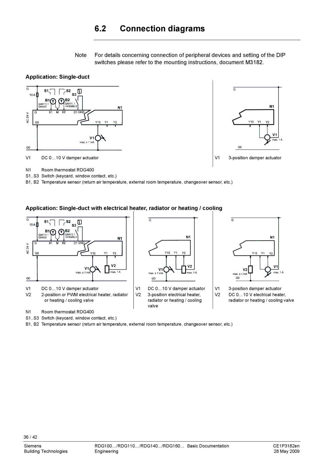
Application: Single-duct
S3 ![]()
V1 |
V1 |
V1 DC 0…10 V damper actuator
V1
N1 Room thermostat RDG400
S1..S3 Switch (keycard, window contact, etc.)
B1, B2 Temperature sensor (return air temperature, external room temperature, changeover sensor, etc.)
Application:
S3 ![]()
V1 | V2 | V2 | V1 |
| V1 | V2 |
V1 | DC 0…10 V damper actuator | V1 | DC 0…10 V damper actuator | V1 | |
V2 | V2 | V2 | DC 0…10 V electrical heater, | ||
| or heating / cooling valve |
| radiator or heating / cooling |
| radiator or heating / cooling valve |
|
|
| valve |
|
|
N1 | Room thermostat RDG400 |
|
|
|
|
S1..S3 | Switch (keycard, window contact, etc.) |
|
|
|
|
B1, B2 | Temperature sensor (return air temperature, external room temperature, changeover sensor, etc.) | ||||
36 / 42
Siemens | RDG100…/RDG110…/RDG140.../RDG160… Basic Documentation | CE1P3182en |
Building Technologies | Engineering | 28 May 2009 |