MSM80C154S MSM83C154S
Page
Contents
Reset Schmitt trigger circuit CPU internal status by reset
2.5.2
2.5.3
2.5.4
Power down mode
3.4.2 T2EXtimer/counter 2 external flag input detector
3.1
Special function registers for serial port 101 2.1
Multi-processor systems 128
129
140
142
KW Pull-Up Resistance Setting for Quasi-bidirectional Input
207
208
210
Introduction
Page
Introduction
MSM80C154S/MSM83C154S/MSM85C154HVS Outline
MSM80C154S/83C154S/85C154HVS
MSM80C154S/MSM83C154S Features
MSM80C154S/83C154S/85C154HVS
Additional Features in MSM80C154S/MSM83C154S/MSM85C154HVS
MSM80C154S/83C154S/85C154HVS
System Configuration
Page
MSM80C154S/MSM83C154S/MSM85C154HVS Logic Symbols
MSM80C154S/MSM83C154S pin layouts
MSM80C154SRS/MSM83C154SRS
MSM80C154S/MSM83C154S pin layout top view
Applicable Packages
1 MSM80C154S/MSM83C154S external dimensions
MSM80C154S/MSM83C154S external dimensions
MSM80C154STS/MSM83C154STS
2 MSM85C154HVS pin layout and external dimensions
MSM85C154HVS pin layout and external dimensions
Signal
TIMER/COUNTER 0&1 Interrupt Serial IO
Special Function
Register Address
ROM Special
DPL PLA Register Address
Sense AMP
TH1 TL1 TH0 TL0 Tmod Tcon
Signal DPH
T2CON TL2 TH2 AMP ACC TR2 TR1
Address Decoder
TH1 TL1 TH0 TL0
Timing and Control
Outline of MSM80C154S/MSM83C154S timing
Timing
9MSM80C154S/MSM83C154S
Major synchronizing signals
External program memory read cycle timing chart
Movx A, @Rr
XTAL1 ALE Psen Inst PORT-0 PCL OUT PORT-2 PCH OUT
12 MSM80C154S Movx @Rr, a execution
13 MSM80C154S Movx A, @DPTR execution
MOV direct, Port 0, 1, 2, 3 execution
XTAL1 ALE Psen
PIN Data CPU Data PIN Data Stable Sampled
4 MSM83C154S fundamental operation time charts
16 MSM83C154S Movx A, @Rr execution
18 MSM83C154S Movx A, @DPTR execution
19 MSM83C154S Movx @DPTR, a execution
PIN Data PIN Data Stable CPU Data Sampled
20 MSM83C154S MOV direct, PORT0, 1, 2, 3 execution
Instruction Register IR and Instruction Decoder PLA
AIR
PLA Wair
PLA WIR
Arithmetic Operation Section
PSW0D0H CY AC F0 RS1 RS0 OV F1 P
Program Counter
CPU Internal Data BUS
Program Memory and External Data Memory
24 MSM80C154S/MSM83C154S program area
ALE Latch
System Configuration
Dptr
XTAL1 ALE Psen
Page
MSM80C154S/MSM83C154S
By register R0 or R1
Data
Control
Page
Crystal resonator connection diagram
Oscillators XTAL1 XTAL2
Supply of 50% duty clock
Clock XTAL2
CPU Resetting
CPU Reset Control
Outline
ROM mode
5Resetexecution
Chart
Chart
XTAL1 Psen ALE
MSM80C154S/83C154S/85C154HVS Reset Schmitt trigger circuit
Reset Schmitt trigger gate detector time chart
CPU internal status by reset
Denotes direct resetting even if XTAL1·2 has stopped
MSM80C154S/MSM83C154S reset internal status
EA CPU Memory Separate
Internal Specifications
Page
Internal Specifications
Internal Data Memory RAM and Special Function Registers
Data memory and special function register layout
Internal Data Memory RAM
Internal data memory RAM
RAM layout diagram
Internal data memory registers R0 thru R7
Program status word PSW
RS0
User Data RAM
MSM80C154S/83C154S/85C154HVS Stack
Stack storage layout
PC5
PC1
Lnternal Data Memory RAM Operating Procedures
Internal data memory indirect addressing
DEC Rr bit arrangement Register designation table
Internal data memory 1-bit data designation
CLR bit address bit arrangement
Bit designation table
Addressing combination table
2AH 2BH
2EH
Special Function Registers TCON, SCON,.... ACC, B
List of special function registers
Special function registers 4.4.2.1 Timer mode register Tmod
MSM80C154S/83C154S/85C154HVS Power control register Pcon
Timer control register Tcon
SCON.6 SM1 SM0 Mode
MSB LSB Scon
SM0 SM1 SM2 REN TB8 RB8
SCON.0
Interrupt enable register IE
MSB LSB
ET2 ET1 EX1 ET0 EX0
ET2
MSM80C154S/83C154S/85C154HVS Interrupt priority register IP
PCT PT2 PT1 PX1 PT0 PX0
PCT
Program status word register PSW
MSM80C154S/83C154S/85C154HVS 2.8 I/O control register Iocon
Timer 2 control register T2CON
TF2 EXF2
EXEN2
TF2
Timer/Counters 0, 1 and 2 4.5.1 Outline
Timer/counters 0 and 1 4.5.2.1 Outline
Timer/counter 0 and 1 counting control
Timer control register Tcon 88H
Circuit for timer/counters 0
Overall clock input control
Timer mode register Tmod 89H
External clock detector circuit for timer/counters 0
Timer
PD & HPD
Counting control of timer/counters 0 and 1 by INT pin
Detector circuit operational time chart
Timer Clock
Timer Gate TR0 INT0 RUN Stop TR1 INT1
Detector
11 Timer mode register Tmod 89H
Timer Counter
Mode
T0 PIN Detector Port TR0 Gate INT0 PIN Data
Detector TF0 TL0 TH0 5BITS 8BITS
T1 PIN Detector Port TR1 Gate INT1 PIN Data
Latch Detector TF1 TL1 TH1 5BITS 8BITS O Clock
MSM80C154S/83C154S/85C154HVS Mode
Detector TF0
TH0 8BITS
Latch Detector TF1
TH1 8BITS O Clock
MSM80C154S/83C154S/85C154HVS Mode
T0 PIN Detector Port TF0
8BITS TR0 Gate
INT0 PIN 8BITS Data
Reload Data Xtal
Detector TF0 T0 PIN Detector Port TR0 Gate INT0 PIN Data
Latch Xtal
TL0 8BITS Detector TF1
TH0 C 8BITS
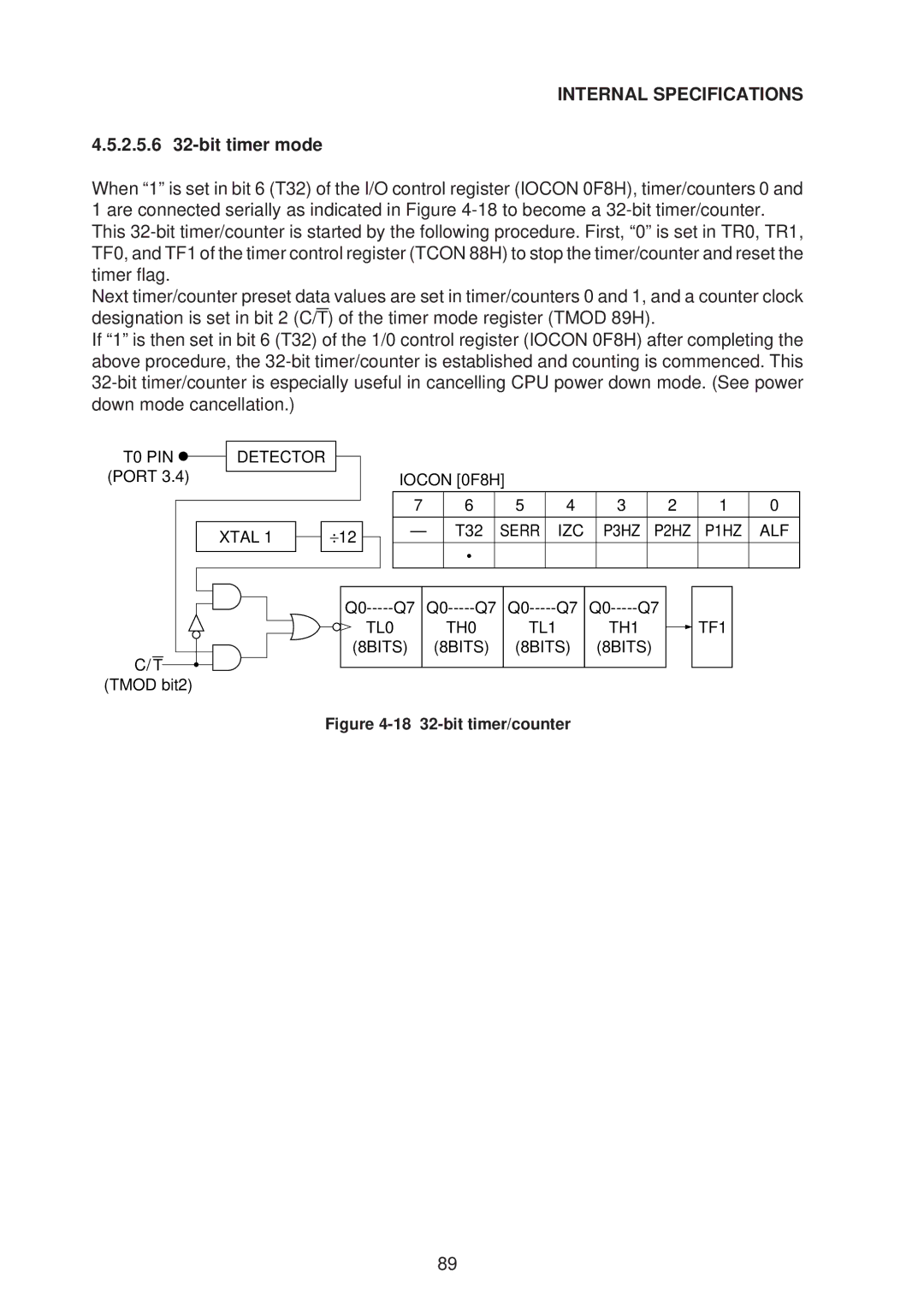
2.5.6 32-bit timer mode
T0 PIN Detector
Iocon 0F8H
Serr IZC
Timer Reset
19 T0, T1 external clock detector circuit
Internal Specifications
Mode 1 or 3 has been set
12 Timer 2 control register T2CON 0C8H
Bit is 0, and valid when
Must be reset to 0 by software
Timer/counter 2 operation modes
3.3.1 16-bit auto reload mode
To 0 by software
3.3.2 16-bit capture mode
TR2 Detector EXEN2 RCAP2L RCAP2H TF2 Timer EXF2 Interrupt
RCLK=0 TCLK=0
TL2 TH2 BIT
3.3.3 16-bit baud rate generator mode
21 Timer/counter 2 16-bit capture mode circuit
Baud
3.4.2 T2EX timer/counter 2 external flag input detector
Reset Timer Counter Clock
Reset Timer Counter T2EX
Timer/counter detector circuit
Detector PD & HPD O Clock
Serial Port
100
RX Control Input Shift Register
Sbuf R
Internal Specifications
102
15 Scon
Sbuf serial port buffer register
Tclk
Rclk
16 Serial port operation modes
MSM80C154S/83C154S/85C154HVS Smod
Serr
Mode 0 baud rate
Mode 0 transmit operation
Mode 0 receive operation
Port mode
107
Serial port mode
Timing chart
108
109
MSM80C154S/83C154S/85C154HVS Mode Outline
Mode 1 baud rate
Mode 1 transmit operation
Mode 1 receive operation
MSM80C154S/83C154S/85C154HVS Mode 1 Uart error detection
Internal BUS TIMER/COUNTER1 SMOD=1 Overflow SMOD=0
113
Start Serr RXD
114
Mode Outline
Mode 2 baud rate
Mode 2 transmit operation
Mode 2 receive operation
Mode 2 Uart error detection
Internal BUS Write Start TBB Sbuf TXD To Sbuf
Baud Rate SMOD=1 Clock XTAL1·2 Couter SMOD=0 Serial Port
118
Mode 3 baud rate
Mode 3 transmit operation
Mode 3 receive operation
Mode 3 Uart error detection
122
123
QHSHIFT/ Load Serial Clock
Inhibit F E D C B a Input
RXD PX.X TXD
RX.X TXD
Qhqg QF QE Qdqc QB QA
CLK
RXD TXD PX.X
PX.X RXD TXD
126
SHIFT/ Load Serial Clock
Output PX.X Control
RXD Input PX.X Control TXD
42 lnput/output extension example timing chart
127
MSM80C154S/83C154S/85C154HVS Multi-processor systems
TXD RXD
Master Slave
Interrupt
18 lnterrupt addresses
130
Interrupt control
Equivalent circuit
19 lnterrupt enable register IE, 0A8H
ET1
PX1
20 nterrupt priority register IP, 0B8H
Priority interrupt routine flow
Clrea
21 Non-priority interrupt order of preference
External interrupt signal 0 and 1 level detection
22 TCON88H register
TF1 TR1 TF0
IE1 IT1 IE0 IT0
External interrupt signal 0 and 1 trigger detection
BUS Tcon Reset
Page
139
Page
141
Page
143
Page
145
CPU Power Down
Idle mode Idle setting
Xtal TIMER, S-I/O Interrupt
147
Xtal Control PCON, 87H Smod HPD RPD GF1 GF0 IDL
23 CPU pin details in idle mode
148
Idle
149
55Idlemodesettingtime
150
Soft power down mode PD setting
Mode equivalent circuit
152
CPU Clock
Pcon 87H Control Smod HPD RPD GF1
Pdreset
Reset END
PCON5RPD Pdreset
153
TIMER0
154
24 CPU pin details ALF=0 in soft power down mode PD
155
Soft power down mode setting
Time chart internal ROM mode
156
Soft
25 CPU pin details ALF=1 in soft power down mode PD
158
Down
159
63Softpowerdownmodesetting
160
Hard power down mode HPD setting
Hard power down
162
Xtal Hpdi Control Pcon 87H Smod HPD RPD GF1 GF0 IDL
26 CPU pin details ALF=0 in hard power down mode HPD
163
164
Mode
165
27 CPU pin details ALF=1 in hard power down mode HPD
166
167
68Hardpowerdownmodesetting
168
Cancellation by CPU resetting Reset pin
By reset internal ROM mode
170
MSM80C154S/83C154S/85C154HVS
171
172
By reset external ROM mode
173
Mode by reset internal ROM mode
174
Mode by reset external ROM mode
175
29 Power control register Pcon 87H
Smod HPD RPD GF1 GF0 IDL
IDLE, PD Mode Interrupt Restart
177
INT
179
Internal ROM mode
180
181
IDLE, PD Mode Restart Mode SET Smod HPD RPD GF1 GF0
OUT Level Sense
Restart from idle mode by
Or 1 external ROM mode
184
Or 1 internal ROM mode
185
External ROM mode
186
Internal Specifications
Back up with hard power down mode
188
189
Back
INPUT/OUTPUT Ports
190
Page
Outline
Port
Port 0 internal equivalent circuit
193
Internal BUS Read
WPO Modify
194
Port 0 pin table
Port
196
Control Modify Port Read WP1
Port 1 internal equivalent circuit
197
OFF
Internal BUS Read OFF
198
199
On P3 On P2 Internal BUS Readoff N
200
Port 1 CPU control pin table
Port 1 pin table
PC/DATA
DPH Port Read Modify WP2 Control
Port 2 internal equivalent circuit
202
PORT2
Internal BUS Control Modify Read Data
WP3
204
Port 3 CPU control pin function table
Port 3 pin table
INPUT/OUTPUT Ports
Power Down Iocon 0F8H
206
Modify Port Read Internal BUS
INPUT/OUTPUT Ports
CPU 1 OUT
12 NPN transistor direct connection circuit
209
CPU 0 OUT
Port Output Timing
One machine cycle instruction output timing
16 Two machine cycle instruction port output time chart
Two machine cycle instruction output timing
Port Data Manipulating Instructions
213
MSM80C154/83C154/85C154
214
Electrical Characteristics
Absolute Maximum Ratings
Operational Ranges
DC Characteristics
VCC=4.0 to 6.0V,VSS=0V, Ta=-40C to +85C
Port 0, ALE, Psen
SSV IV CC
218
DC Characteristics
219
Repeated for specified input pins
Repeated for specified output pins
Measuring circuits
Input logic for specified status
External Program Memory Access AC Characteristics
222
External program memory read cycle
ALE Psen Port
Instr
External Data Memory Access AC Characteristics
Output
224
External data memory read cycle
External data memory write cycle
Output Data Setup to Clock Rising Edge TQVXH
226
Machine Cycle ALE Shift Clock Output Data Input Data
AC Characteristics Measuring Conditions
Input/output signal
Floating
Test Point
Exterminal Oscillator Signal
XTAL1 External Clock Input Waveform Conditions
Description of Instructions
Page
Description of Instructions
Description of Instruction Symbols
List of Instructions
MSM80C154S/MSM83C154S
Instruction table
Simplified Description of Instructions
Address in this description
235
CLR a CPL a RL a RLC a RR a RRC a Swap a
236
XRL
MOV
238
MOV Dptr
CLR
Setb
239
Movc A, @A+PC
240
Interrupt Enable Ajmp
Ljmp
Sjmp
JMP @A+DPTR
242
Then Else Cjne
243
Then Else Djnz
244
245
External RAM
Movx A, @DPTR
NOP
Detailed Description of MSM80C154S/MSM83C154S Instructions
Acall code address Absolute call within 2K bytes
ADD A, #data Add immediate data
247
RS1
MSM80C154S/83C154S/85C154HVS ADD A, @Rr Add indirect address
248
ADD A, Rr Add register
249
MSM80C154S/83C154S/85C154HVS ADD A, data address Add memory
250
Addc A, #data Add carry plus immediate data to accumulator
251
252
ADD A, Rr Add carry plus register to accumulator
253
254
Ajmp code address Absolute jump within 2K byte
255
256
ANL A, @Rr Logical and indirect address to accumulator
257
258
ANL A, data address Logical and memory to accumulator
259
260
ANL C,/bit address Logical and complement bit to carry flag
261
262
ANL data address, a Logical and accumulator to memory
263
264
265
LOC OBJ Source
Testajmp TEST1
Compcjne @R1, #05H, Test
266
267
Cjne A, #0AH, SS1 LOC OBJ Source
SS1MOV R7, a
Compcjne A, #0AH, SS1
268
269
Cjne A, 50H, Next LOC OBJ Source
Compcjne A, 50H, Next
Callcall Test
270
Compared data is not equal. If the compared data is equal
271
Countinc R4
MSM80C154S/83C154S/85C154HVS CLR a Clear accumulator
272
CLR C Clear carry flag
273
MSM80C154S/83C154S/85C154HVS CLR bit address Clear bit
274
CPL a Complement accumulator
275
MSM80C154S/83C154S/85C154HVS CPL C Complement carry flag
276
CPL bit address Complement bit
277
MSM80C154S/83C154S/85C154HVS DA a Decimal adjust accumulator
278
279
280
DEC a Decrement accumulator
281
MSM80C154S/83C154S/85C154HVS DEC Rr Decrement register
282
DEC data address Decrement memory
283
MSM80C154S/83C154S/85C154HVS DIV AB Divide accumulator by B
284
AC F0 RS1 RS0 OV F1
285
286
Djnz R1, Loop LOC OBJ Source
Loopadd A, R7
Countdjnz R1, Loop
287
288
Djnz 57H, Loop LOC OBJ Source
Countdjnz 57H, Loop
INC @Rr Increment indirect address
289
MSM80C154S/83C154S/85C154HVS INC a Increment accumulator
290
INC Dptr Increment data pointer
291
RS1 RS0 PSW
DPH DPL
MSM80C154S/83C154S/85C154HVS INC Rr Increment register
292
INC data address Increment memory
293
294
295
Bittsjb 34.3, Enter
ACA0 Entermov R4, 0A0H
296
297
298
299
Checkacall Addr
Jmpcjc Carry
Carryinc @R1
300
Byte Description
JNB bit address, code address Jump if bit is not set
301
302
Testjnb 37.3, Exit
Exitmov A, @R0
JNC code address Jump if carry is not set
303
304
Testjnc Exit
Exitmov B, ACC
JNZ code address Jump if accumulator is not
305
306
JNZ Test LOC OBJ Source
Checkjnz Test
Testmov R3, a
JZ code address Jump if accumulator is not
307
308
JZ Empty LOC OBJ Source
Emptyinc a
Checkjz Empty
Lcall code address Long call
309
MSM80C154S/83C154S/85C154HVS Ljmp code address Long jump
310
MOV @Rr, #data Move immediate data to indirect address
311
6AH
312
6CH
MOV @Rr, data address Move memory to indirect address
313
314
MOV A, @Rr Move indirect address to accumulator
315
316
MOV A, data address Move memory to accumulator
317
318
MOV DPTR, #data Move immediate data to data pointer
319
DPH·DPL
320
MOV Rr, a Move accumulator to register
321
322
5AH
MOV bit address, C Move carry flag to bit
323
324
MOV data address, @Rr Move indirect address to memory
325
326
MOV data address, Rr Move register to memory
327
6BH
328
329
Movc A, @A+DPTR
330
331
62CCH
332
333
DPL DPH
57AFH
334
MUL AB Multiply accumulator by B
335
MSM80C154S/83C154S/85C154HVS NOP No operation
336
ORL A, #data Logical or immediate data to accumulator
337
338
ORL A, Rr Logical or register to accumulator
339
340
ORL C, bit address Logical or bit to carry flag
341
342
ORL data address, #data Logical or immediate data to memory
343
344
POP data address Pop stack to memory
345
346
RET Return from subroutine, non interrupt
347
348
RL a Rotate accumulator left
349
RS1 RS0 OV F1 P PSW
350
RR a Rotate accumulator right
351
352
Setb C Set carry flag
353
MSM80C154S/83C154S/85C154HVS Setb bit address Set bit
354
Sjmp code address Short jump
355
356
Sjumpsjmp Check
Checkrlc a
357
358
Subb A, Rr Substract register from accumulator with borrow
359
360
Swap a Exchange nibble in accumulator
361
362
XCH A, Rr Exchange register with accumulator
363
364
7AH
365
366
367
368
369
370
371