Circuit breaker

For safety work on a pump unit, install a circuit breaker as close as possible to the machine. It also is advisable to place an earth fault circuit breaker. The switching equipment must comply with prevailing regulations, as stipulated by EN 60204-1.

Motor overload protection

To protect the motor against overloads and short-circuits a thermal or thermo-magnetic circuit breaker must be incorporated. Adjust the switch for the nominal current absorbed by the motor.

Connection

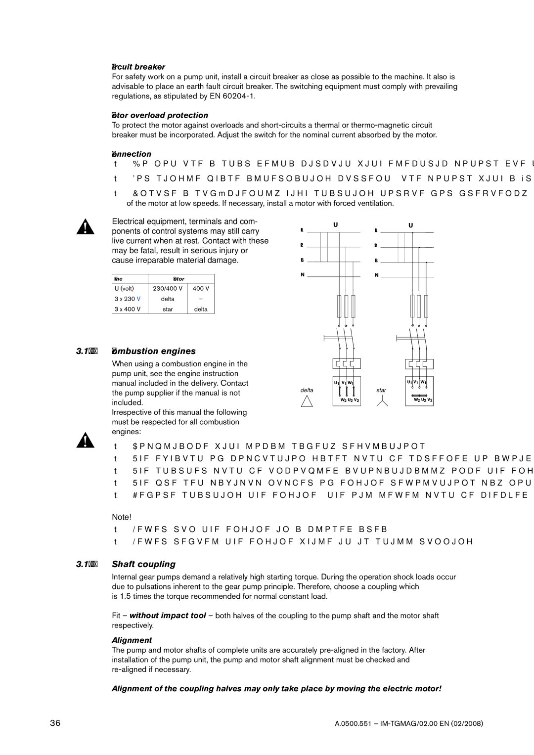
Do not use a star-delta circuit with electric motors due to the required high starting torque.

For single-phase alternating current, use motors with a “reinforced” starting torque.

Ensure a sufficiently high starting torque for frequency-controlled motors and adequate cooling of the motor at low speeds. If necessary, install a motor with forced ventilation.

Electrical equipment, terminals and com- ponents of control systems may still carry live current when at rest. Contact with these may be fatal, result in serious injury or

L1

L2

U

L1

L2

U

cause irreparable material damage.

Line

Motor


U (volt)

230/400 V


400 V

3 x 230 V

delta


3 x 400 V

star


delta


L3

N

L3

N

3.18.7.5 Combustion engines

When using a combustion engine in the pump unit, see the engine instruction manual included in the delivery. Contact the pump supplier if the manual is not included.

Irrespective of this manual the following must be respected for all combustion engines:

delta

U1

V1 W1

W2 U2 V2

star

U1 V1 W1

W2 U2 V2

Compliance with local safety regulations

The exhaust of combustion gases must be screened to avoid contact

The starter must be uncoupled automatically once the engine has started

The pre-set maximum number of engine revolutions may not be modified

Before starting the engine, the oil level must be checked

Note!

Never run the engine in a closed area

Never refuel the engine while it is still running

3.18.7.6Shaft coupling

Internal gear pumps demand a relatively high starting torque. During the operation shock loads occur due to pulsations inherent to the gear pump principle. Therefore, choose a coupling which

is 1.5 times the torque recommended for normal constant load.

Fit – without impact tool – both halves of the coupling to the pump shaft and the motor shaft respectively.

Alignment

The pump and motor shafts of complete units are accurately pre-aligned in the factory. After installation of the pump unit, the pump and motor shaft alignment must be checked and re-aligned if necessary.

Alignment of the coupling halves may only take place by moving the electric motor!

36

A.0500.551 – IM-TGMAG/02.00 EN (02/2008)

Page 36
Image 36
SPX Cooling Technologies TG MAG15-50, TG MAG185-125, TG MAG58-80, TG MAG23-65 Combustion engines, Shaft coupling

TG MAG86-100, TG MAG23-65, TG MAG58-80, TG MAG15-50, TG MAG185-125 specifications

SPX Cooling Technologies has established itself as a leader in the design and manufacturing of cooling systems, offering a wide range of products tailored to meet specific industrial and commercial needs. Among its impressive lineup, the TG MAG series stands out, featuring models such as TG MAG185-125, TG MAG23-65, TG MAG86-100, TG MAG58-80, and TG MAG15-50. Each of these models combines innovative technology with robust performance characteristics, making them ideal choices for various applications.

The TG MAG185-125 model is designed for high-capacity cooling requirements, offering exceptional thermal performance while maintaining energy efficiency. Its advanced fan design minimizes noise levels, making it suitable for installations in noise-sensitive areas. Furthermore, the unit benefits from a corrosion-resistant construction, ensuring longevity and reliable operation in diverse environments.

For smaller applications, the TG MAG23-65 provides a compact solution without compromising on performance. This unit features a space-efficient design and utilizes high-efficiency fans that optimize airflow, thereby enhancing overall cooling efficiency. The integrated digital controls allow for precise temperature management, making it easy for operators to monitor and adjust settings as needed.

The TG MAG86-100 model serves as an ideal middle-ground solution, balancing capacity and efficiency. It incorporates state-of-the-art technology, such as variable speed drives, which adjust the fan speed based on cooling demand, resulting in significant energy savings. The design also promotes easy maintenance, with accessible components that facilitate regular servicing and inspections.

For medium-scale needs, the TG MAG58-80 combines durability with performance, featuring a robust frame that can withstand harsh operational conditions. Its efficient heat exchange technology maximizes cooling output while minimizing energy consumption. Moreover, the enhanced airflow system ensures uniform cooling across the entire unit.

Lastly, the TG MAG15-50 is perfect for smaller spaces where cooling requirements are less demanding. Despite its size, this model is equipped with cutting-edge features such as a compact structure and highly efficient cooling mechanisms to ensure effective performance. The easy installation process and low maintenance needs further enhance its appeal.

Overall, the TG MAG series provides a range of innovative cooling solutions tailored to meet diverse industrial requirements, characterized by efficiency, durability, and advanced technology, ensuring optimal performance across all operating conditions.