Contents
Models
MANUAL
PUB-GS0597B Rev.
RGXI800,*RGX2400,. RGX3500,RGX5500 Generators
Page
Page
RGX2400
I ~~
RGX1800
cu. in
RGX3500
RGX5500
2.PERFOMANCE CURVES
bkc1.5k
1.5k 1k
n t-
CURRENT A +
I- 3 n I-
2+-2MODEL RGX2400
I- 3
CURRENT A+ 0 4 a 12 16 CURRENT A\+
CURRENT A”
1k 3
CURRENT A+
0102030
4 8 12 -16
120 110
Page
CURRENT A
i, z
CURRENT A
W 3 U W
a. t
2-4MODEL RGX5500
61 60
4k-t
51 50
0 5 10 15 20
CURRENT AI
I:,6k c5
in total
3 a 3 -2k o
r l k
3.FEATURES
4.GENERAL DESCRIPTION OF THE GENERATOR
7NKCAP
RGX2400 50HZ-11OV, 60Hz-12OV TYPE
4-2CONTROL PANEL
0RGXl800 50HZ-11OV, 60Hz-120V TYPE
VOLTMETER
F U L L POWER SWITCH
DCFUSE DC OUTPUT TERMINAL
220V RECEPTACLE\ DC OUTPUT TERMINAL
Page
I AC 22OVl
TJ 0+
I AC 220V
RGXI800,2400 :SWITZERLAND, 50Hz-220V
RGXl800,2400 :AUSTRALIA, 5OHZ-240V
RGX3500 50H~-220V,240V, 60Hz-220VTYPE
RGX3500 :50HZ-11OV, 60Hz-120VTYPE
Option
Option’
RGX3500 :GERMANY, 50Hz-220V
RGX3500 :U.S.A., 60H~-120V/24OVNEMARECEPTACLE
220v RECEPTACLE
Option \
EARTH GROUND TERMINAL
DC OUTPUT TERMINAL
Option
RGX3500 :AUSTRALIA, 50HZ-24OV
RGX5500 :50Hz-11OV, 60Hz-120VTYPE
START
RGX5500 :50H~-22OV,240V, 60Hz-220V TYPE
RGX5500 :SOHZ, 60Hz-110V/220V TYPE
220v RECEPTACLE
GROUNDTERMINALDCOUTPUTEARTH
RGX5500 :GERMANY, 50Hz-220V
RGX5500 :50Hz-220V WITH SPECIAL RECEPTACLE
Page
LABEL, MODEL NAME
5-2 FUNCTION 5-2-1STATOR
5.CONSTRUCTIONANDFUNCTION
5-1 CONSTRUCTION
5-2-3 ROTOR
5-2-2 CONDENSER
11ov,
I 1 1
5-24FUSE
5-26 NO-FUSEBREAKER
Page
Fig.
5-3 DESCRIPTION of GENERATOR OPERATION
5-3-1 GENERATION Of NO-LOADVOLTAGE
5-3-2 VOLTAGEFLUCTUATIONSUNDERLOAD
Fig.
Switch
LOWER VOLTAGE
HIGHER VOLTAGE
5-34 VOLTAGE CHANGEOVER SWITCH
6. SAFETY PRECAUTIONS
7. RANGE OF APPLICATIONS
The smaller the motor, the lower the efficiency
Voltage drop indicates as V =
f2 means the length of the wire m
8. MEASURING PROCEDURES
II !jr-
b/---.--j
j:1:. /iii!
4CIRCUIT TESTER
Use a “Dr. Robin”generator tester in megger tester mode or use a megger tester to check the insulation resistance. Connect a megger tester to one of receptacle output terminals and the ground terminal, then measure the insulation resistance. An insulation resistance of 1 megohm or more is normal. The original insulation resistance at the time of shipment from the factory is 10 megohm or more
Measure the insulation across one of the soldered
Replace the faulty part
terminals of the rotor and the core
9. CHECKING FUNCTIONAL MEMBERS
9-4STATOR
9-3CIRCUIT BREAKER
Page
nNORMAL CAPACITY OF CONDENSER
IO. DISASSEMBLY AND ASSEMBLY
DISASSEMBLY
pannelof control box
1RemoveSIDE PLATE from frame SeeFig
3.PipeFrame
Remove the mount rubbers from SIDE PLATE
3Dismountthe engineand alternatorfrom the frame
4.Rear Cover 1 Removetheendcover. SeeFig. 10-l1
Staitor
6. Rotor
6.Rotor
1 Removethe front cover
7.Front Cover
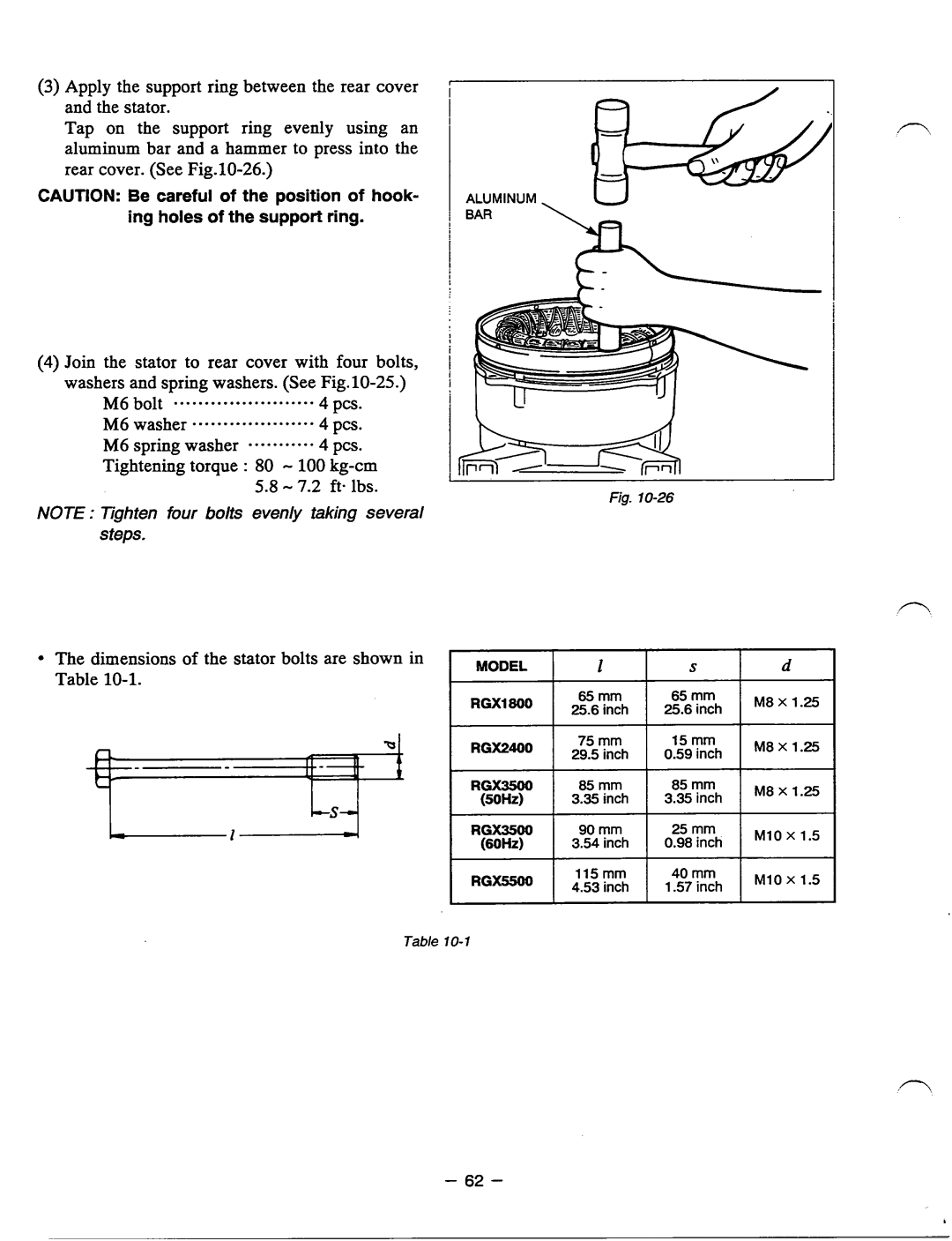
Loosen the four bolts and remove the
wrench
M8 X 18mm bolt . . . . . .4 pcs
M6 bolt ... .. . .. . .. .. .. ... ... .. 4 pa
M6 X 25 mm bolt *.***----..*..4 pcs
Attach the end cover to the rear cover
M8 nuts Tightening torque : 120 - 140 kg-cm
4Mount the control box to the frame
washers “.~..““..““
Dismount the control box from frame
11. TROUBLESHOOTING
1 CHECKING FIELD COIL
Page
If the appliance is faulty, repair it
Check the fuse in the fuse holder
1Inspect the solenoid bracket
ASingle Voltage Type
Check the FUSE on wiring of IDLE CONTROL UNIT
12. WIRING DIAGRAM
r--1
1.25 mm2
0.75mm2
1.25
1.25 mm2
1 SC
lRGX3500 : SOHz, 6OHz-1lOW22OV TYPE
lRGX3500 : U.K.., SOHz-1lOW22OV BS RECEPTACLE
0.75
r--1
1 LLEb
O-75mm
I -L
0.75
eP-l I I
1.25
Page
ENGINE
0.75
1.25
= .-_
Page
CONTROL BOX
0.75
vc SW
I I I
PRINTED IN THE USA
I\ America