Cabling the Server
Connect the server power cables, and external cables in the following order:
1. Connect two grounded server power cords to grounded electrical outlets (1, 2).
Note – Connect only one cable if your server does not have a redundant power supply.
2.Connect the two server power cords to the AC power connectors on the back panel of the server.
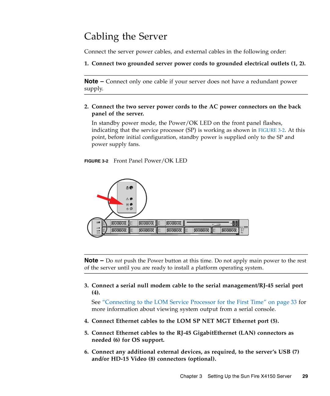
In standby power mode, the Power/OK LED on the front panel flashes, indicating that the service processor (SP) is working as shown in FIGURE
FIGURE 3-2 Front Panel Power/OK LED
Note – Do not push the Power button at this time. Do not apply main power to the rest of the server until you are ready to install a platform operating system.
3.Connect a serial null modem cable to the serial
(4).
See “Connecting to the LOM Service Processor for the First Time” on page 33 for more information about viewing system output from a serial console.
4.Connect Ethernet cables to the LOM SP NET MGT Ethernet port (5).
5.Connect Ethernet cables to the
6.Connect any additional external devices, as required, to the server’s USB (7) and/or
Chapter 3 Setting Up the Sun Fire X4150 Server | 29 |