Back Panel
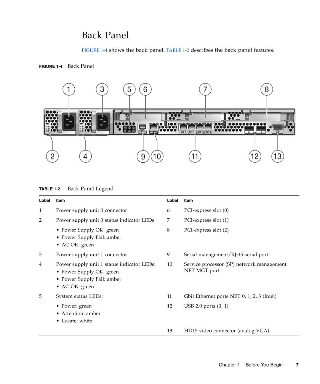
FIGURE 1-4 shows the back panel. TABLE 1-2 describes the back panel features.
FIGURE 1-4 Back Panel
TABLE 1-2 Back Panel Legend
Label | Item | Label | Item |
|
|
|
|
1 | Power supply unit 0 connector | 6 | |
2 | Power supply unit 0 status indicator LEDs | 7 | |
| • Power Supply OK: green | 8 |
•Power Supply Fail: amber
•AC OK: green
3 | Power supply unit 1 connector | 9 | Serial |
4 | Power supply unit 1 status indicator LEDs: | 10 | Service processor (SP) network management |
| • Power Supply OK: green |
| NET MGT port |
•Power Supply Fail: amber
•AC OK: green
5 | System status LEDs: | 11 | Gbit Ethernet ports NET 0, 1, 2, 3 (Intel) |
| • Power: green | 12 | USB 2.0 ports (0, 1) |
•Attention: amber
•Locate: white
13 HD15 video connector (analog VGA)
Chapter 1 Before You Begin | 7 |
