SUPERSERVER
5-8 Connector Definitions
ATX Power
Pin Definitions (JPW1)
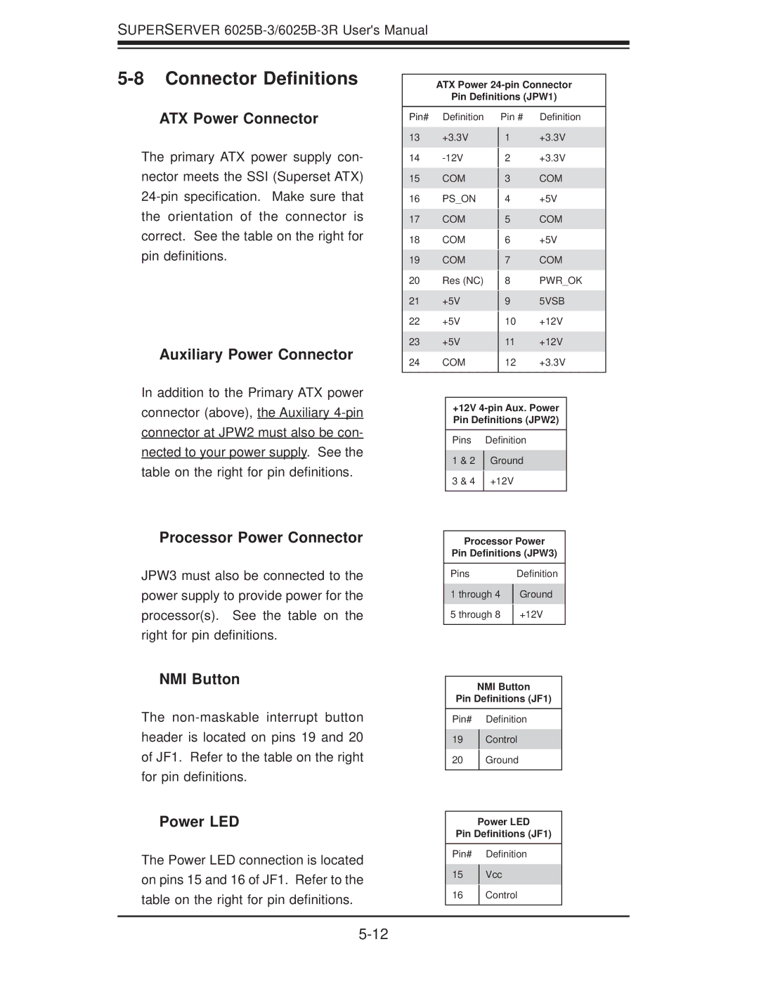
ATX Power Connector
The primary ATX power supply con- nector meets the SSI (Superset ATX)
Auxiliary Power Connector
Pin# Definition
13+3.3V
14
15COM
16PS_ON
17COM
18COM
19COM
20Res (NC)
21+5V
22+5V
23+5V
24COM
Pin # Definition
1+3.3V
2+3.3V
3COM
4+5V
5COM
6+5V
7COM
8PWR_OK
95VSB
10+12V
11+12V
12+3.3V
In addition to the Primary ATX power connector (above), the Auxiliary
Processor Power Connector
JPW3 must also be connected to the power supply to provide power for the processor(s). See the table on the right for pin definitions.
NMI Button
The
Power LED
The Power LED connection is located on pins 15 and 16 of JF1. Refer to the table on the right for pin definitions.
+12V
Pins |
| Definition |
1 & 2 |
| Ground |
| ||
3 & 4 |
| +12V |
| ||
|
|
|
Processor Power
Pin Definitions (JPW3)
Pins |
| Definition |
1 through 4 |
| Ground |
| ||
5 through 8 |
| +12V |
| ||
|
|
|
NMI Button
Pin Definitions (JF1)
Pin# Definition
19Control
20Ground
Power LED
Pin Definitions (JF1)
Pin# Definition
15Vcc
16Control