SUPERSERVER
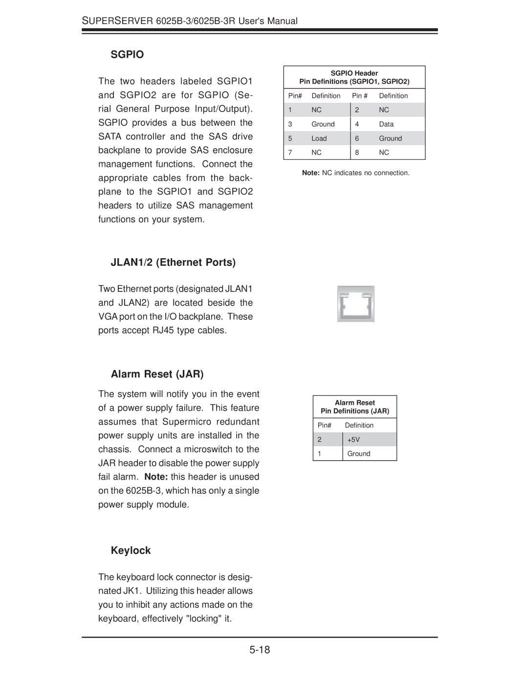
SGPIO
The two headers labeled SGPIO1 and SGPIO2 are for SGPIO (Se- rial General Purpose Input/Output). SGPIO provides a bus between the SATA controller and the SAS drive backplane to provide SAS enclosure management functions. Connect the appropriate cables from the back- plane to the SGPIO1 and SGPIO2 headers to utilize SAS management functions on your system.
SGPIO Header
Pin Definitions (SGPIO1, SGPIO2)
Pin# | Definition | Pin # | Definition |
1 | NC |
| NC |
2 | |||
3 | Ground |
| Data |
4 | |||
5 | Load |
| Ground |
6 | |||
7 | NC |
| NC |
8 | |||
|
|
|
|
Note: NC indicates no connection.
JLAN1/2 (Ethernet Ports)
Two Ethernet ports (designated JLAN1 and JLAN2) are located beside the VGA port on the I/O backplane. These ports accept RJ45 type cables.
Alarm Reset (JAR)
The system will notify you in the event of a power supply failure. This feature assumes that Supermicro redundant power supply units are installed in the chassis. Connect a microswitch to the JAR header to disable the power supply fail alarm. Note: this header is unused on the
Keylock
The keyboard lock connector is desig- nated JK1. Utilizing this header allows you to inhibit any actions made on the keyboard, effectively "locking" it.
Alarm Reset
Pin Definitions (JAR)
Pin# Definition
2 +5V
1 Ground