SC743 Chassis Manual
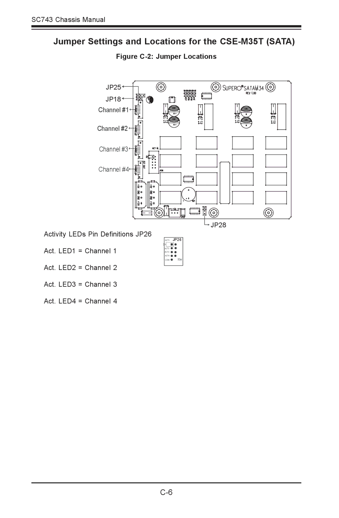
Jumper Settings and Locations for the CSE-M35T (SATA)
Figure C-2: Jumper Locations
JP25![]()
JP18![]()
![]()
![]()
![]()
![]()
![]()
Channel #1![]()
![]()
Channel #2![]()
![]()
![]()
Channel #3![]()
![]()
![]()
Channel #4![]()
![]()
![]()
Activity LEDs Pin Definitions JP26
Act. LED1 = Channel 1
Act. LED2 = Channel 2
Act. LED3 = Channel 3
Act. LED4 = Channel 4
![]()
![]() JP28
JP28
ACT1 | JP26 |
ACT2 |
|
ACT3 |
|
ACT4 |
|
COM | Key |
